Then the engagement force Np, Ng and friction force Fp, Fg can be expressed as:
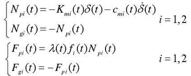
Where: lambda (t) is the directional coefficient of the friction force on the tooth surface, when the friction force is in line with the forward direction of the X coordinate, “+” and its direction changes through the joint position during engagement; () if t is (i) its direction changes through the joint position during engagement; () if t is the time-varying friction coefficient, which is related to the roughness of the tooth surface, lubrication conditions and relative slip speed, and will be analyzed in detail later;Indicates the first pair of gears.
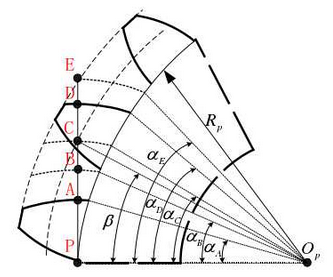
In order to accurately describe the engagement position and state, the gear deployment angle alpha is introduced. After determining the gear parameters and installation center distance, each engagement key point (A-E) corresponds to a unique deployment angle as shown in Figure 2.4.In the figure beta is the actual engagement angle.
Thus the friction directional coefficient can be defined:

Where mod () is a redundancy operation and sign () is a sign function.Alpha D A_a is one of them, mod () is a redundancy operation and sign () is a sign function.D Aalpha_alpha is the angle of extension corresponding to a single pitch and C A_alpha is the angle of extension corresponding to the passing through the joint from the starting point of engagement, i.e. when the engagement point passes through the joint, the direction coefficient changes from positive to negative.
The dynamic control equations of X and Y direction translation and rotation of active and passive gears are established:
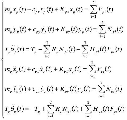
In the formula above, the friction arm can be defined based on the deployment angle as follows:
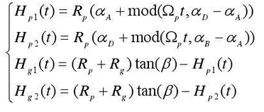
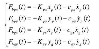
The dynamic bearing force is calculated by the following formula: