
Preface
Independent operation and maintenance is the key to continuously promote the construction and expansion of intelligent manufacturing in recent years.The inevitable stage of green and low-carbon manufacturing coverage is green factories,Intelligent manufacturing demonstration factory and independent optimization of the best performance of excellent scenariosand reflect the scale and capability of the enterprise’s intelligent manufacturing operation and maintenance team constructionExpanding performance assessment.The electric spindle is an essential tool for the rotary transmission of CNC equipment.At the user’s site, there are often lathe electric spindles, machining center electric spindles,Grinder electric spindle and grinder electric spindle, etc. 11-axis 6-linkage made in GermanyThe A, B, and C axes of the spiral bevel gear machine tool (hereinafter referred to as C50) are allThe electric main motor is composed of Siemens 1FW6230 torque motor as the main component.The constant low temperature and long-term operation of the shaft are the rigid requirements of end users.Over the past 3 years, 3 C50s have experienced water leakage/blockage during use,The electric spindle is burned out, accompanied by errors in the 611D or S120 series drive system and servo failure.Eight C50s are symmetrically arranged on four flexible production lines.On the production line, the 3 malfunctioning machines are located on 3 of the production linesThis requires the operator to repeatedly switch between tooling and clamping jaws.The cutting task of the rear axle bevel gear pair was completed, resulting in the final gear pairAbnormal production.
Application and maintenance status of domestic and foreign electric spindles
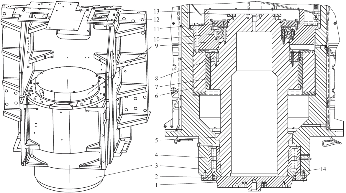
C50 is a method of using continuous or individual indexing toAll pitch forms of spiral bevel gears and hypoid bevel gears are carried outbulk dry cutting (using carburized hardened metal milling cutters)High-efficiency CNC machine tools.It involves three vertical structural arrangements and direct transmissionDriving system – tool driving system, workpiece driving system and base angle drivingThe tool drive system includes the A-axis, which controls the rotation of the tool,X-axis for tool cutting depth feed and stroke of 610mm (milling)depth), Y-axis for horizontal positioning of the tool with a stroke of 820mm,The Q axis that controls the rotation of the chamfering milling cutter and the X2 axis for positioning, A axis axial directionThe circular runout and radial runout shall not exceed 0.4μm;the workpiece drive systemIt includes the B-axis that controls the rotation of the workpiece and the X-axis and Y-axis that are used for horizontal positioning of the workpiece.The axial and radial runouts of the Z and B axes with a stroke of 230mm are bothNot exceeding 0.8μm;the base angle drive system only has one for the workpiece swingC-axis (base angle) with control and rotation range of ±87°.The German solution to the problem of burning down the electric spindle is to adopt a modular designThe replacement of large parts A and B axes costs nearly 5.58 million yuan for 3 sets, with a maintenance cycle ofA total of 365 days;the additional condition is that the replaced defective parts are free of chargeIt was shipped back to Germany.In 2017, the A axis of the C50 was disassembled and repaired in China.The result is that the arc tooth surface has vibration marks – the tooth surface feels uneven.The integrated upper and lower feeding manipulators lose their automatic function,The operator can only manually load and unload materials using electric hoists.For the B axis of the electric spindle, there has never been on-machine repair in China, and there is no experience to draw on.There is only one macroscopic overview diagram for each of the A and B axes in the C50 random atlas, of whichThe macro view of Axis A is shown in the figure. In order to play the role of green factory, intelligent manufacturing demonstration factory and excellentTo achieve the best performance of the scene, it is necessary to develop the “arc tooth bevel gear machineThe application research of electric spindle in bed.
15 scientific and technological innovation points of electric spindle application projects
There are 15 technological innovation points in the application of electric spindle projects:Make A, B axis puller to take out the electric spindle on the machine, and make A, B axis rigidThe protective frame enhances safety, and the self-made motor stator reinforcement ring prevents deformationShape [2], self-made U-shaped flat plate with B-axis hoisting, self-made cross beam hoistingThe A-axis stator coil is completed by using spacer pads to complete the connection between the torque motor stator andThe rotor is embedded, and a self-made screw-type traction tool is used to install the electric spindle.The supporting wheel is used to carry the wet chip removal machine, and the Ghost function can be used to restore the PCU50 with one click.Hard disk data, equipped with a hammer-type copper rod to install an electric spindle, self-made “digging”Take out the workpiece disc spring with an ear spoon and use a PWT18 quick adjustment instrument to adjust itMeasuring Heidenhain grating ruler, eliminating vibration on the arc tooth surface, installing C50 machineFully integrated SPL function processing, as well as MDA cycle program search and cuttingSudden stop.
Self-made A and B axis puller to remove the electric spindle on the machine
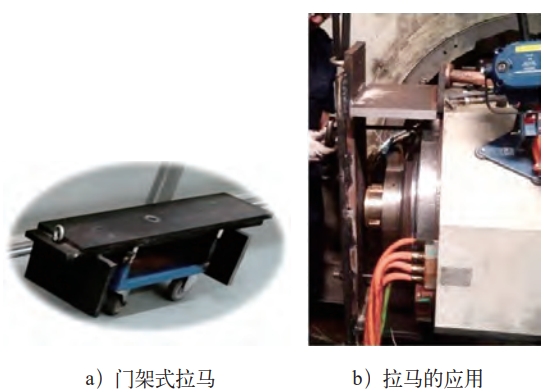
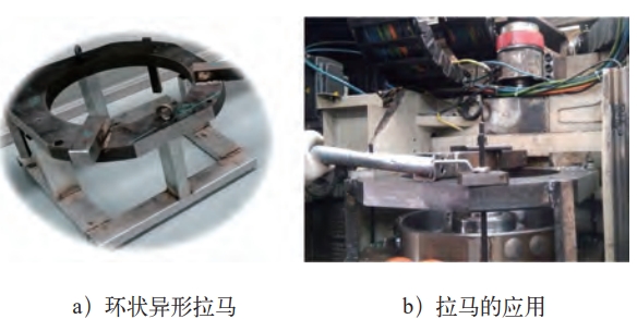
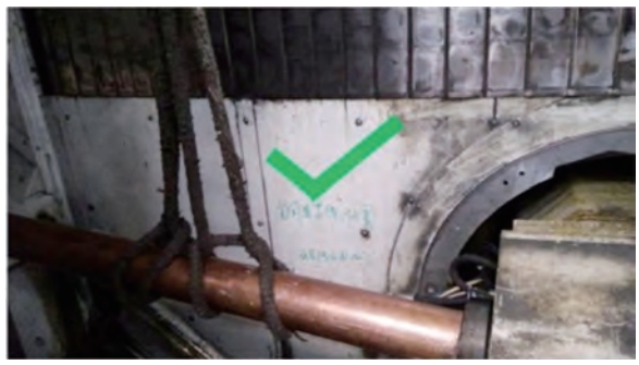
Inspired by the three-claw and four-claw pullers on the market, combined with the position structure of the B-axis, a 40mm thick steel plate was used to create a B-axis disassembly door.Rack-type puller (see figure), which can automatically control the torque of 1FW6230 electricThe entire electric spindle consisting of machine parts and components is pulled out.The A axis of C50 is limited by the space of the machine body, with ribs on both sidesBoard, only design ring shaped shaped puller (see picture).It is made of 50mmIt is made of thick sheet metal, with 2 legs on the bottom and 2 “ears” on the sideThe two “ears” are placed on the white triangular rib plate in the picture.Realize the overall extraction of the electric spindle.
Self-made A and B axis rigid protective frame to enhance safety
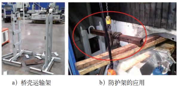
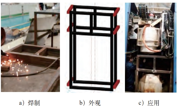
Considering the safety of maintenance personnel, a special rigid anti-vibration device for A and B axes is produced.Protective frame.Figure 4 shows the B-axis rigid protective frame, which is made of local materials and uses the bridge housingThe transport frame is restructured, that is, it is cut in half, which can only accommodateA narrow maintenance space for 1 person, avoiding the overall sliding of the electric spindle.
The A-axis rigid protective frame (see Figure 5) is fully protected by the middle part of the machine tool.For good B-axis influence, only spliced protective frames can be designed, that is, pre-installedWeld two large pieces first, place them under the A axis of the body, and then use red80mm square tube short rib beam is bolted.In this way, the machine tool can beThe overall protective cover can prevent the vertical shaft from sliding down.
Self-made motor stator reinforcement ring to prevent deformation
The stator coil frame of the 1FW6230 torque motor is made of aluminum.During the process of strong disassembly and hoisting, it is easy to be squeezed and deformed, which will affect the subsequent installation.Serious damage may cause the motor to be scrapped.Therefore, the design and production ofThe sub-reinforcement ring (see figure) is pre-tied to the stator coil and then mounted via the eyebolt.
Self-made U-shaped flat plate with hoisting B axis
The maximum swing angle of the C axis is ±87°, which cannot be arranged horizontally.so that the B-axis cannot be removed and replaced horizontally.To avoid a 3° installation tiltThe diagonal angle challenges the strength of the maintenance personnel’s waist, using a 40mm wide, 2mm thick5mm flat iron is used to make U-shaped flat plate belt (see figure), replacing soft rope andSingle lifting point.
Self-made cross beam for hoisting A-axis stator coil
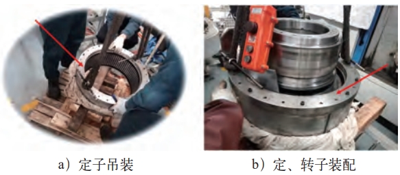
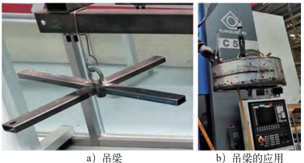
The vertical A-axis is different from the horizontal B-axis disassembly.The B-axis interiorIt is hollow, allowing the B-axis rotor and stator to be removed and replaced together.The A-axis isSolid and only one M16 blind hole in the middle, making it necessary toFirst remove the rotor, then take out the stator.The outer ring of the stator and the wall of the housing holeThe clearance is only 1mm, which requires alignment and lifting.Therefore, a specialUse a cross beam (see Figure 8) to attach it to the stator coil.
Completing the embedding of the torque motor stator and rotor with spacers
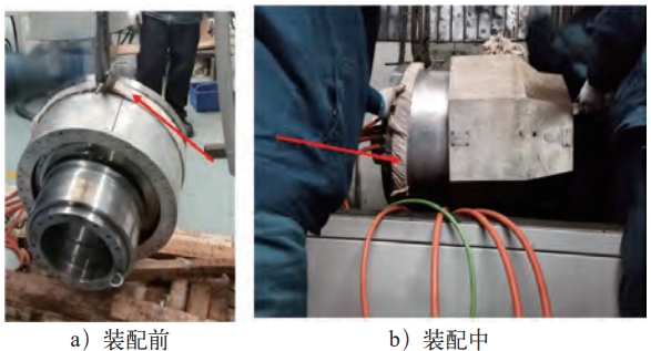
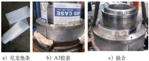
The rotor of the 1FW6230 torque motor is a permanent magnet, and the statorFor the coil winding, the gap between the two is about 0.5mm. During installation,When the rotor is rotating, the strong suction force will cause the stator and rotor to be attracted together.Therefore,Before installation, three nylon strips with a width of 190mm and a thickness of 0.5mm must be prepared.One person controls the stator coil to fall, and three people control the nylon pad to be inserted into the stator and rotor.Pull out the nylon pad with the rotor as it falls, until the rotor is completely seated.The lower end of the sub-coil is closely attached to the end face base of the electric spindle.After manyAfter disassembling the electric spindle, it was found that the nylon gasket was not as good as the A3 rubber sleeve. NowAll of them should be replaced with A3 rubber sleeves.The nylon pad and A3 rubber sleeve are shown in the figure.
Installing an electric spindle for a self-made screw-type traction tool
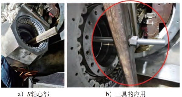
The B-axis installation of C50 uses a screw-type traction tool, reversing the gantry puller and using its plane, the middleThe φ26mm through hole penetrates the M24×1000mm screw and penetrates the B axis centerThe screw is inserted into the 80mm square tube.Adjust the position and gradually pull it to the endRemove the cover when the outer ring enters the B-axis housing and the remaining 10mm is leftUse a screw-type traction tool with a 120mm diameter copper rod.
Self-made supporting wheel for carrying wet chip removal machine
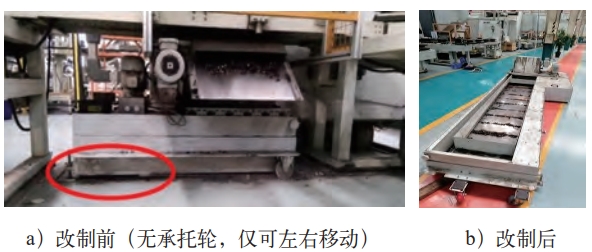
Some C50 machines are equipped with wet chip removal machines below the screen, which requires self-screening.Operation side access.After the production line is completed and 2 sets of C50 are symmetrically arranged,After the machine is turned off, the chip removal machine lacks access space, and can only be unloaded from the circularThe line is drawn out of the gap, which requires the modification of the supporting wheel to increase the supportBoard, to change the directional wheel to a universal wheel.The supporting wheel of the wet chip removal machine is changedThe situation before and after the system is shown in the figure.
One-click Ghost recovery of industrial control computer hard disk data
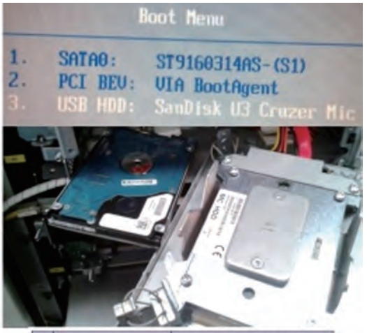
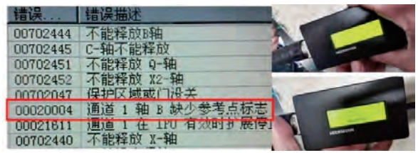
After the C50 electric spindle is carefully installed, users expect it to operate without any worries.But in actual operation, the operator sometimes reports alarm messages such as synchronous errors in the rotor position displayed on the screen and servo failures.After continuously adjusting the position and restarting the device for several times, the C50 can enterworking state, but it needs to be adjusted laboriously every 8 hours.After trying to clear all the NC and PLC data of C50, the staff producedEBOOT USB boot disk for SINUMERIK 840D systemRun Ghost with one click, and paste the security integration function into the serverInside the drive.
Configure hammer-type copper rod to install electric spindle
Due to the large interference fit between the outer ring of the B-axis end cap and the inner hole of the housing,In addition, the NNU double-row cylindrical roller bearing is installed together, resulting inThe front screw-type traction tool cannot pull them into the last 10mm.At this time, use a φ120mm×1000mm hammer-type copper rod to knock the entire electric spindle into the casing, similar to the “harmony” in the temple.Still ring the bell.Remember: Do not use excessive force to avoid causing Z-axis straight lines.The guide rail slider is broken and the reading head of the grating ruler is damaged.
Self-made “ear-pick” to remove the workpiece disc spring
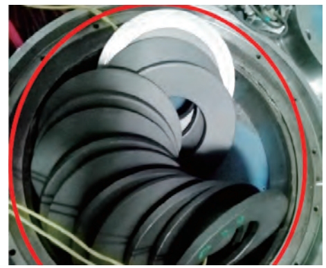
In the disassembly of the B-axis, a relatively small “ear-pick” will be usedIt is used to disassemble 12 pieces of DIN2093 arranged in positive and negative order in the B axis center.Disc spring A180 Gr3.Use your left hand to gently hold the material of 50CrVA orFor the 50CrV4 disc spring, pull the “ear-pick” outward with your right hand to remove the disc springs one by one.The function of the disc spring isProvide 4.0×10⁴N tension, tighten the workpiece;rely on it when loosening the workpiece1.6MPa air pressure compresses the Belleville spring to complete the task of loosening the workpiece.
Select PWT18 fast adjustment instrument to adjust the grating ruler
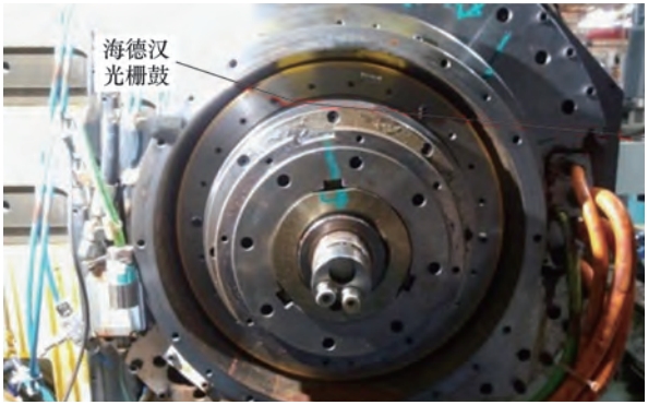
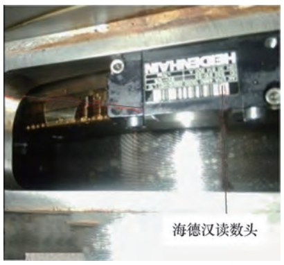
The rotational positions of the A, B, and C axes are determined by the grating drum and theThe reading heads on the non-moving side are coupled to each other to provide real-time feedback of coordinate data.The installation clearance between the grating drum and the reading head is (0.1±0.015) mm,If the gap is large, the distance is not calculated, and if the gap is small, the steel belt is rubbed and the reading is damaged.Now, with the help of the PWT18 grating ruler quick adjustment instrument (see Figure 15)Adjust the gap to make the grid amplitude around 1Vss (within the allowable range0.6-1.2Vss), the black bars of the origin signal are always at twoIn square brackets.The grid amplitude measured in PWT18 is 0.82-0.97VssWhen running, C50 will display multiple alarms, causing servo failure.
radical treatment of vibration on the tooth surface of arc tooth
Comprehensive use of graphical monitoring, parameter optimization, instrument measurement, etc.Modular operation and maintenance techniques for analyzing the true cause of tooth vibration,Effective measures for eliminating tooth cutting vibration are given.All C50 fixturesReplace it with a new one, and optimize the speed loop of Axis B (MD1200=3 → 4,MD1219=510 → 1080, MD1220=150→500,MD1407=12000 → 15000), change the tensioning method of the fixture(Remove the air circuit P120.60 and replace it with a pure Belleville spring tension, Fz=4.2kN → 4.7kN), optimizing the cutting process parameters.
The whole machine is equipped with SPL function for security integration
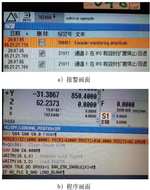
Once the safety integration chain of C50 is triggered, the signal $A_PLCSIIN and $A_PLCSIIN have abnormal conditions, which leads toThe loading door cannot be opened and closed normally.Therefore, an 8-line 1-program is adopted to break throughThe SPL loading door has no action problem, and the 8-wire is controlled by electricity.N900-N901, N902-N903, N567-N267 andN667-N376.
MDA cycle program to search for cutting tooth stop
For multi-axis CNC machine tools, MDAThe loop program will search for the root cause of the screen alarm and will play a role in preventing the occurrence of the problem.For example, the vertical axis X axis is programmed in the MDA modeWhen the process cycle is running, maintenance personnel can analyze the noise and monitor the rollingCheck the load of the ball screw pair and ensure the ball screw nut pair is in good working conditionStatus: The oscillating axis C axis is programmed to run in a cyclic and reciprocal manner in MDA modeWhen the maintenance personnel can determine the actual angle of the C-axis screen display alarm, they can modify the C-axis parameters and spend money to upgrade the COP32 program instead.operation, thereby eliminating the shutdown fault of the C axis.
Conclusion remarks
Intelligent manufacturing operation and maintenance teamIn this case, the use of electrical signal deduction, mechanical action coupling, and workUsing the medium flow method, complete the on-machine disassembly of the water-cooled electric spindle, andSuccessful reinstallation and recovery;using the one-click Ghost of the industrial control computer hard disk dataTechniques and servo drive optimization technology quickly eliminate the occurrence of self-repairof various alarms and mechanical and electrical failures.Formed a perfect water-cooled electric spindleIndependent operation and maintenance process, for lathe spindle, machining center spindle,Operation and maintenance of grinder electric spindle and knife grinder electric spindle provide referencecase。