
In the development of space robotics, there is a growing demand for compact, simple, and highly reliable mechanical transmission mechanisms for robot end-effectors used in orbital capture and servicing tasks. Worm gears offer inherent advantages such as self-locking capability, large reduction ratio in a single stage, and orthogonal shaft arrangement, making them particularly suitable for gripper-type end-effectors. However, the space environment imposes extreme challenges including high vacuum, severe temperature cycling, vibration during launch, and radiation. The applicability of worm gears in such conditions has not been thoroughly investigated. In this study, we systematically address the key issues of installation, lubrication, vibration resistance, thermal adaptability, and lifetime of worm gears used in a space manipulator end-effector. Through combined analytical and experimental approaches, including thermal vacuum chamber tests and vibration table tests, we demonstrate that with proper design, worm gears can meet the stringent requirements of space missions. This paper presents our comprehensive investigation and provides practical guidelines for the space application of worm gears.
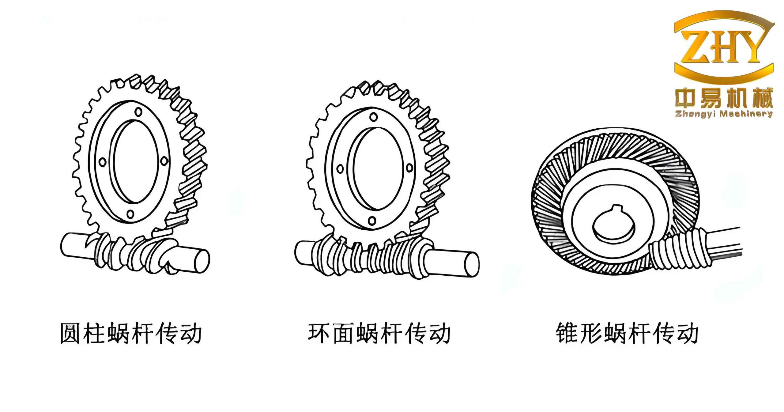
1. Design and Analysis of the Worm Gear Pair
The end-effector we developed adopts a parallel-jaw gripper configuration with symmetrical opening and closing motion. To achieve this, a single worm driving two worm wheels was selected as the core transmission mechanism. The worm axis coincides with the main shaft of the gripper, and the two worm wheels are symmetrically arranged on both sides, enabling synchronized finger motion. This compact layout reduces the number of components and simplifies the control logic.
The worm gear pair must withstand both the static and dynamic loads during launch and in-orbit operations. The worm material was chosen as 9Cr18 stainless steel with localized carburization to achieve a hardness of HRC 50, preventing corrosion in humid pre-launch conditions. The worm wheel was made of QSn6.5 phosphor bronze to provide good wear resistance and low friction. The basic parameters were: module \( m = 1 \), worm pitch diameter \( d_1 = 14 \, \text{mm} \), nominal center distance \( a = 32 \, \text{mm} \), and output torque on the worm wheel \( T_2 = 3 \, \text{N·m} \).
We performed contact and bending strength checks. The actual contact stress was calculated as:
$$ \sigma_H = Z_E \sqrt{ \frac{2 T_2}{d_1 d_2 m \epsilon_\alpha} } \approx 166 \, \text{MPa} $$
which is below the permissible contact stress of 234 MPa. The safety factor against tooth root bending fracture was 2.74, exceeding the typical requirement for general machinery.
To account for the severe vibration environment during rocket launch, we introduced a simplified impact model. Under the assumption that the worm gear is not locked (worst case), the vibration-induced impact on the worm wheel teeth was approximated as a reverse rotation impact. The impact force on the worm wheel due to sinusoidal vibration can be expressed as:
$$ F_{\text{imp}} = \frac{M G l}{R} = \frac{2 M G l}{m_i} $$
where \( M \) is the mass of the finger payload, \( G \) is the vibration acceleration amplitude, \( l \) is the distance from the mass center to the worm wheel axis, \( R \) is the worm wheel pitch radius, and \( m_i \) is the number of teeth in contact. The number of impact cycles during the vibration event is \( n = f T \), where \( f \) is the vibration frequency and \( T \) is the duration. This impact cycle count was used to verify the contact fatigue life of the worm gear pair after launch vibration.
2. Center Distance Analysis Under Thermal Cycling
In the vacuum of space, heat transfer is limited to conduction and radiation, leading to significant temperature gradients within the worm gear assembly. For example, the worm wheel bearing housing and the worm wheel shaft can experience a temperature difference of up to 50 °C. These thermal gradients cause differential thermal expansion of components made from different materials, altering the center distance between the worm and worm wheel. If not properly accounted for, the gear pair may jam or experience excessive backlash.
We modeled the center distance deviation due to manufacturing tolerances and assembly clearances. The total radial clearance contributed by the worm wheel side is:
$$ X_L = X_{LZW} + X_{LZN} + X_{LZ} + X_{LLZ} + X_{LL} $$
where \( X_{LZW} \) is the clearance between worm wheel bearing and its housing, \( X_{LZN} \) is the clearance between bearing and worm wheel shaft, \( X_{LZ} \) is the shaft runout, \( X_{LLZ} \) is the clearance between worm wheel bore and shaft, and \( X_{LL} \) is the concentricity error of the worm wheel bore relative to its pitch circle.
Similarly, for the worm side:
$$ X_G = X_{GZW} + X_{GZN} + X_{GZ} $$
where \( X_{GZW} \), \( X_{GZN} \), and \( X_{GZ} \) are the corresponding clearances for the worm bearing housing, bearing-shaft fit, and shaft runout.
The thermal expansion contribution to center distance increase for the worm wheel assembly is:
$$ X_{LT} = \Delta T \left[ (\rho_{\text{Ti}} – \rho_{\text{steel}}) \cdot L_W + (\rho_{\text{steel}} – \rho_{\text{Ti}}) \cdot L_N + (\rho_{\text{bronze}} – \rho_{\text{Ti}}) \cdot L_Z – \rho_{\text{bronze}} \cdot L \right] $$
where \( \rho_{\text{Ti}} \), \( \rho_{\text{steel}} \), and \( \rho_{\text{bronze}} \) are the thermal expansion coefficients of titanium (bearing housing), steel (shaft and worm), and bronze (worm wheel), respectively. \( L_W \), \( L_N \), \( L_Z \), and \( L \) represent characteristic dimensions. For the worm side:
$$ X_{GT} = \Delta T \left[ (\rho_{\text{Ti}} – \rho_{\text{steel}}) \cdot G_W – \rho_{\text{steel}} \cdot G \right] $$
The total maximum center distance deviation due to all factors is:
$$ X_{\text{total}} = X_L + X_G + X_{LT} + X_{GT} $$
Therefore, the actual center distance we designed was \( a + X_{\text{total}} + \Delta a + X_{\text{safety}} \), where \( \Delta a \) is the nominal backlash and \( X_{\text{safety}} \) is an additional margin to avoid jamming under extreme temperature gradients.
3. Lubrication of Worm Gears in Vacuum
Space lubrication aims to reduce friction, prevent cold welding, and maintain consistent performance over the mission lifetime. Traditional liquid lubricants (oils) are difficult to seal in the worm gear housing, and ordinary greases may suffer from evaporation or solidification under vacuum and temperature extremes. Therefore, we evaluated three lubrication options: MoS₂ sputtered solid film, Shell MP5 grease, and Braycote 601 grease.
We conducted a run-in test on a worm gear pair lubricated with MoS₂ solid film. After a short running period, the black MoS₂ film on the tooth surfaces was severely worn away, as confirmed by visual inspection. The solid film could not maintain a continuous lubricating layer under the sliding and rolling contact of worm gears, making it unsuitable for this application.
Next, we tested Shell MP5 grease. At room temperature, the efficiency was acceptable, but when the temperature dropped below −15 °C, the worm gear pair exhibited stall due to excessive grease viscosity. This low-temperature failure made MP5 unsuitable for the wide temperature range of space (typically −40 °C to +70 °C).
Finally, we selected Braycote 601, a perfluoropolyether (PFPE) based grease designed for space use. We measured the efficiency across the temperature range using a torque sensor. The results are summarized in Table 1.
| Temperature (°C) | Input Torque (N·m) | Output Torque (N·m) | Efficiency (%) |
|---|---|---|---|
| −40 | 0.50 | 0.08 | 16 |
| −20 | 0.50 | 0.10 | 20 |
| 0 | 0.50 | 0.14 | 28 |
| 25 | 0.50 | 0.17 | 34 |
| 60 | 0.50 | 0.19 | 38 |
The efficiency ranged from 16% to 38% over the temperature range, which was acceptable for the gripper application where high torque and self-locking are more critical than efficiency. The bearings supporting the worm and worm wheels were lubricated with MoS₂ solid film, which is standard for space ball bearings.
4. Sealing Design for Grease Retention
Since the grease used for the worm gear pair is incompatible with the MoS₂ solid lubricant in the bearings (the grease can wash away the solid film), we needed a reliable sealing system to prevent grease migration. Labyrinth seals were installed at all six rotating interfaces: two at the worm shaft ends and two at each worm wheel shaft end. The labyrinth seals provide a tortuous path that restricts grease flow while maintaining low friction torque.
The radial clearance in the labyrinth seal changes with temperature due to differential thermal expansion. The total radial deviation due to manufacturing and assembly is:
$$ Y_L = X_{LZW} + X_{LZN} + Y_K + Y_J + Y_M + Y_Z + Y_{TM} + Y_{TZ} $$
where \( Y_K \) is housing runout, \( Y_J \) is assembly gap, \( Y_M \) is labyrinth runout, \( Y_Z \) is worm wheel shaft runout, and \( Y_{TM} \) and \( Y_{TZ} \) are bore and shaft tolerances respectively.
At low temperature, the labyrinth clearance reduces by:
$$ Y_{LT} = \Delta T (\rho_{\text{Al}} – \rho_{\text{Ti}}) \cdot L_M $$
where \( \rho_{\text{Al}} \) is the expansion coefficient of the aluminum labyrinth ring, \( \rho_{\text{Ti}} \) is for the titanium housing, and \( L_M \) is the labyrinth length. The total worst-case radial deviation is \( Y = Y_L + Y_{LT} \). We designed the labyrinth bore diameter as \( \phi + Y + \Delta \phi + Y_{\text{safety}} \) to ensure no contact under cold conditions.
5. Vibration Test Validation
To simulate the launch environment, we performed sine-sweep and random vibration tests on the worm gear based end-effector. The input conditions are listed in Table 2.
| Frequency range (Hz) | Longitudinal amplitude | Lateral amplitude | Sweep rate |
|---|---|---|---|
| 10–20 | 8.44 mm | 7.03 mm | 4 dB/Oct |
| 20–100 | 13.5 g | 11.25 g | |
| 20–100 | 16.2 g | 13.5 g |
We measured the worm gear efficiency before and after the vibration test to check for any degradation. The efficiency curve shifted slightly upward after vibration, likely due to run-in effects. No significant change in backlash or noise was observed. This indicated that the worm gears could withstand the launch vibration without damage.
6. Thermal Vacuum Test
The thermal vacuum test assessed the performance of the worm gear pair over a temperature range of −45 °C to +70 °C under vacuum (pressure < 10⁻⁵ Pa). The test lasted for 7 days, with multiple temperature cycles and continuous operation at each plateau as shown in Figure Thermal vacuum profile (not shown here due to referencing limitations). We measured the pulse-width modulation (PWM) value required to initiate motion of the gripper fingers at different positions, as an indicator of starting friction. The results are summarized in Table 3.
| Sequence | Temperature (°C) | Direction | Position 1 | Position 2 | Position 3 | Position 4 | Position 5 |
|---|---|---|---|---|---|---|---|
| 1 | 63 | Forward | −55 | −55 | −55 | −60 | − |
| Reverse | − | +60 | +75 | −75 | +60 | ||
| 2 | −39.5 | Forward | −35 | −35 | −35 | −35 | − |
| Reverse | − | +35 | +35 | +40 | +35 | ||
| 3 | 60.9 | Forward | −60 | −55 | −75 | −75 | − |
| Reverse | − | +75 | +55 | +60 | +60 | ||
| 4 | −40.7 | Forward | −35 | −35 | −35 | −35 | − |
| Reverse | − | +40 | +40 | +40 | +40 | ||
| 5 | 25 | Forward | −60 | −65 | −60 | −60 | − |
| Reverse | − | +65 | +75 | +55 | +75 |
The start-up PWM values remained consistent within a reasonable range across all temperatures, indicating that the worm gear pair maintained stable friction characteristics. No jamming or excessive wear was observed after the full test.
7. Results and Discussion
Based on the experimental campaign, we draw several important conclusions. First, the analytical methods for center distance estimation, including allowances for thermal expansion and assembly tolerances, were validated by the fact that no jamming occurred during the thermal vacuum test. The worm gear pair operated smoothly from −40 °C to +60 °C.
Second, Braycote 601 grease proved to be an effective lubricant for worm gears in space. The measured efficiency, although low (16–38%), was sufficient for the gripper application where the primary requirement is reliable holding and grasping rather than high efficiency. The grease did not evaporate or degrade under vacuum.
Third, the labyrinth seals successfully prevented grease migration into the bearings. Post-test inspection confirmed that the bearing areas remained free of grease contamination, and the MoS₂ solid lubricant films were intact.
Fourth, the vibration test did not harm the worm gears. In fact, the slight efficiency increase after vibration suggests that the tooth surfaces may have experienced beneficial micro-smoothing. The larger backlash intentionally designed into the system helped absorb impact loads without causing excessive wear.
Fifth, the single-worm dual-wheel configuration provided highly symmetrical motion. The measured position repeatability of the fingers was better than 0.1 mm, which meets the typical capture requirements for orbital servicing.
One limitation we observed is that the worm gear efficiency is highly temperature-dependent. In very cold conditions (−40 °C), the torque required to drive the worm increased significantly due to grease viscosity. This must be considered when sizing the motor and electronics for the end-effector.
8. Conclusion
This study systematically addressed the key challenges of applying worm gears in space manipulator end-effectors. Through careful design of center distance, lubrication, sealing, and strength verification, we demonstrated that worm gears can successfully operate under the combined effects of vacuum, temperature cycling, and launch vibration. The main findings are:
- The analytical model for center distance, including thermal and tolerance contributions, is valid and necessary to prevent jamming.
- Braycote 601 space grease is a suitable lubricant for worm gears in vacuum, while MoS₂ film is not adequate.
- Labyrinth seals with proper clearance design can effectively separate grease and solid lubricant systems.
- Worm gears with moderate backlash can withstand launch vibration without significant degradation.
- The single-worm dual-wheel topology is feasible and provides precise symmetrical gripping motion.
Our work provides a practical reference for space engineers considering worm gears as a reliable and compact transmission solution for robotic end-effectors. Future work will focus on optimizing the tooth profile for higher efficiency and investigating the long-term lubricant degradation over multi-year missions. The successful application of worm gears in this prototype paves the way for their inclusion in upcoming orbital servicing and planetary exploration robots.