
Take the center distance between the straight cylindrical gear hob and the straight cylindrical gear α Installation error e α= – 0.05mm, axis intersection angle error E Σ = 0mm. That is, the straight cylindrical gear processed at this time is a negative displacement gear, and the displacement XM = -0.05mm.
As shown in Figure 1, it is the error between the simulated tooth profile of spur gear and the theoretical involute tooth profile when the displacement XM = -0.05mm.

It can be seen from Figure 1 that when the displacement XM = -0.05mm, the error value between the simulated tooth profile and the theoretical involute tooth profile is -23.35 μ m ~ -23.29 μ m。
As shown in Figure 2, it is the displacement XM = -0.5mm. The end tooth profile and theoretical involute tooth profile of spur gear hobbing are obtained by simulation.
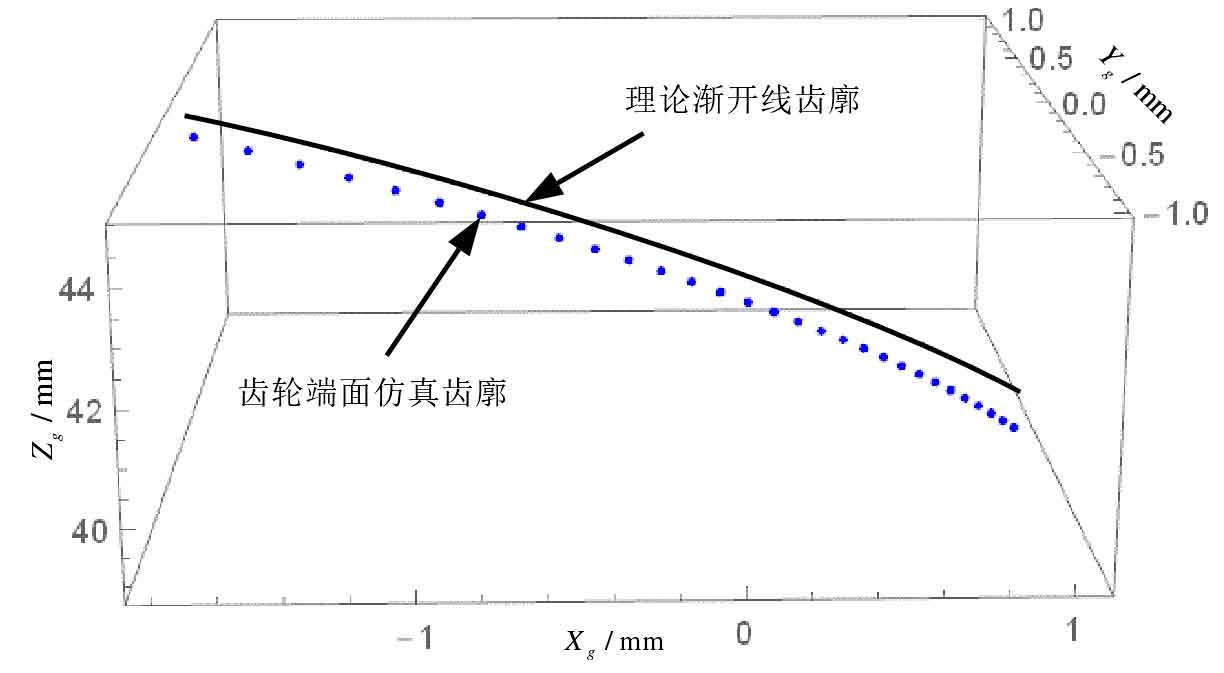
As shown in Figure 3, it is the error between the simulated tooth profile of the end face of spur gear and the theoretical involute tooth profile when the displacement XM = -0.5mm.
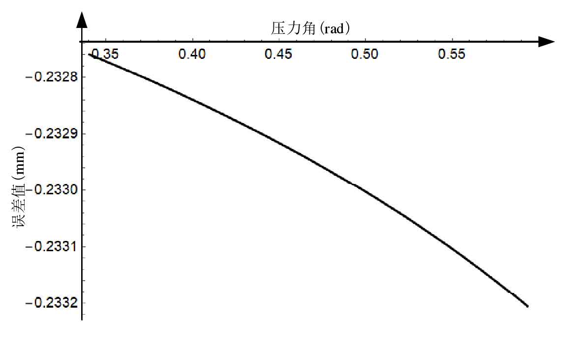
As can be seen from Fig. 3, when the installation center distance error of spur gear hob and gear is e α= – When it is 0.5mm, that is, the displacement XM = -0.5mm, the error value between the simulated tooth profile and the theoretical involute tooth profile is – 232.7 μ m ~ -233.2 μ m 。
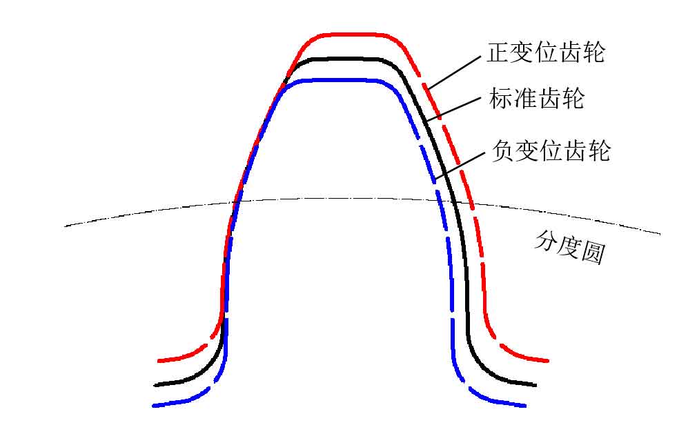
The test of the modified spur gear is simulated by the spur gear hobbing model, as shown in Figure 4. It is the schematic diagram of the modified spur gear, the black solid line is the standard spur gear, the red dotted line is the positive modified spur gear, the blue dotted line is the negative modified spur gear, and the fine dotted line is the graduation circle.