
Abstract
This paper focuses on the modeling and optimization of assembly errors in the spindle cutter disc component of a bevel gear milling machine. By establishing geometric feature error models based on small displacement torsors, analyzing error transmission attributes under series and parallel mating conditions, and proposing a tolerance optimization model considering tolerance cost, assembly accuracy reliability, and tolerance principles, the paper demonstrates an 8.36% reduction in tolerance processing cost while ensuring an assembly accuracy reliability of no less than 97%.
Keywords: small displacement torsor; geometric feature error model; mating surface error; tolerance optimization; bevel gear
1. Introduction
Research on tolerance modeling and optimization has been extensively conducted by scholars both domestically and internationally. However, previous studies have not addressed tolerance modeling for bevel surfaces or assembly errors between planes and bevel surfaces, and most have not considered reliability in tolerance optimization. Therefore, this paper focuses on geometric feature error analysis of bevel surfaces, establishes an error model for parallel mating between cones and planes, and proposes a tolerance optimization model, verifying its application value through case studies on the spindle cutter disc component of a bevel gear milling machine.
2. Geometric Feature Error Modeling
Geometric feature error modeling is the foundation for subsequent error transmission analysis and tolerance optimization. Based on small displacement torsors, error models for various geometric features are established.
Table 1: Geometric Feature Error Models
| Geometric Feature | Error Model Description |
|---|---|
| Cylindrical Surface | Described by position, orientation, and shape errors |
| Planar Surface | Described by position, orientation, and flatness errors |
| Conical Surface | Described by position, orientation, cone angle, and axis straightness errors |
3. Assembly Error Transmission Model
3.1 Mating Surface Error Modeling
The mating surfaces of the spindle cutter disc component mainly include conical mating surfaces, cylindrical mating surfaces, and planar mating surfaces.
Table 2: Types and Error Transmission Attributes of Mating Surfaces
| Mating Surface Type | Error Transmission Attribute |
|---|---|
| Conical Mating Surface | Axial variation described by small displacement torsors |
| Cylindrical Mating Surface | Similar to conical surfaces, with axial and radial variations |
| Planar Mating Surface | Position and orientation variations |
3.2 Error Transmission Calculation for Parallel Mating Surfaces
For parallel mating surfaces, the actual error transmission attributes are solved by determining the mating sequence, checking for interference, and calculating the error transmission matrix.
4. Assembly Accuracy Reliability Analysis and Tolerance Optimization
4.1 Assembly Accuracy Reliability Analysis
Assembly accuracy reliability is evaluated by considering the variation range of error parameters and their impact on assembly accuracy.
4.2 Tolerance Optimization Model
The tolerance optimization model aims to minimize tolerance cost while satisfying assembly accuracy reliability and tolerance design principles.
Table 3: Tolerance-Cost Mathematical Model Parameters
| Geometric Feature | Tolerance-Cost Mathematical Model |
|---|---|
| Planar Feature Size Tolerance & Shape Tolerance | C(T)=5.026e−15.8903T+T0.3927T+0.1176 |
Table 4: Tolerance Values and Ranges for Key Geometric Features
| Geometric Feature | Tolerance Value Range |
|---|---|
| Cylindrical Mating Surface D1 (Inner Cylinder Size Tolerance) | T1∈[0.01,0.03] |
| Conical Mating Surface D2 (Spindle Outer Cone Size Tolerance) | T7∈[0.002,0.02] |
| Planar Mating Surface D3 (Knife Disk Plane Size Tolerance) | T9∈[0.005,0.02] |
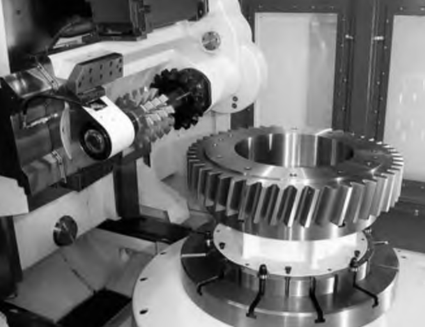
5. Error Transmission Model and Tolerance Optimization for the Spindle Cutter Disc Component
5.1 Error Transmission Model
The error transmission model for the spindle cutter disc component considers the error transmission from the cylindrical mating surface to the precision output plane of the knife disk.
Note: The above image is a placeholder. The actual diagram should depict the error transmission path from the cylindrical surface to the knife disk plane.
5.2 Tolerance Optimization Results
Through tolerance optimization, an 8.36% reduction in tolerance processing cost was achieved while ensuring an assembly accuracy reliability of no less than 97%.
Conclusion
This paper presents a comprehensive approach to modeling and optimizing assembly errors in the spindle cutter disc component of a bevel gear milling machine. By establishing geometric feature error models, analyzing error transmission attributes, and proposing a tolerance optimization model, the study demonstrates significant cost savings while maintaining high assembly accuracy reliability. The proposed method has important implications for guiding tolerance design in similar applications.