
In this study, we investigate the axial vibration behavior of a high-speed high-power herringbone gear transmission system. The herringbone gear is widely used in marine propulsion systems due to its high load capacity and low noise. However, under practical operating conditions, axial vibrations induced by manufacturing errors and time-varying mesh stiffness can significantly affect the system’s performance and reliability. We model the herringbone gear as two helical gear pairs with opposite helix angles and axial floatation, using a lumped parameter method to capture all 16 degrees of freedom. The dynamic equations are derived considering time-varying mesh stiffness, transmission errors, helix angle errors, and eccentric errors. Numerical solutions are obtained to examine the forced vibration response. Our results reveal that the primary sources of axial vibration are the helix angle error and the time-varying mesh stiffness, while tooth profile errors have a relatively minor effect. The axial displacement magnitude and its variation with helix angle error are quantified. These findings provide a foundation for the stiffness design of thrust bearings in herringbone gear systems.
1. Introduction
Large marine propulsion systems demand high-speed, heavy-load, and low-noise characteristics. The herringbone gear (also known as double helical gear) is commonly employed in such systems because it can theoretically cancel axial forces through its two oppositely-handed helical gear pairs. However, in reality, manufacturing and assembly imperfections cause an imbalance in axial forces, leading to axial vibrations. These vibrations not only reduce transmission accuracy but also directly affect the clearance of thrust bearings, which are typically hydrodynamic and sensitive to gap variations. Excessive axial displacement may cause direct contact between the shaft end and the bearing housing, resulting in system failure. Moreover, axial vibrations propagate to the propeller, generating additional underwater noise and increasing drag. Therefore, understanding the axial vibration characteristics of herringbone gear transmissions is crucial for improving the performance and reliability of ship propulsion systems. In this paper, we focus on the dynamic modeling and analysis of a high-speed herringbone gear system, emphasizing the influence of helix angle error, time-varying mesh stiffness, and tooth profile error on axial vibration.
2. Dynamic Model of Herringbone Gear Transmission
We treat each herringbone gear as two helical gears rigidly connected via a shaft, forming two helical gear pairs. Each gear is represented as a lumped mass at its center, with four degrees of freedom: two transverse displacements (x, y), one axial displacement (z), and one torsional angle (θ). The system thus has 16 DOF. The shaft segments are modeled as massless springs and dampers in bending, torsion, and axial directions. Gear meshing is represented by a stiffness and damping element along the line of action. The overall coordinate system is fixed with the origin at the center of the driving pinion and the z-axis aligned with the shaft axis.
The dynamic equations for the four gear masses (1,2 on driving shaft; 3,4 on driven shaft) are given below (only one set shown for brevity):
For Helical Gear 1 (driving, left side):
$$
\begin{aligned}
m_1 \ddot{x}_1 + c_{b1,2}(\dot{x}_1-\dot{x}_2) + k_{b1,2}(x_1-x_2) + c_{x1}\dot{x}_1 + k_{x1}x_1 &= -F_{x1,3} \\
m_1 \ddot{y}_1 + c_{b1,2}(\dot{y}_1-\dot{y}_2) + k_{b1,2}(y_1-y_2) + c_{y1}\dot{y}_1 + k_{y1}y_1 &= F_{y1,3} \\
m_1 \ddot{z}_1 + c_{z1,2}(\dot{z}_1-\dot{z}_2) + k_{z1,2}(z_1-z_2) + c_{z1}\dot{z}_1 + k_{z1}z_1 &= F_{z1,3} \\
I_1 \ddot{\theta}_1 + c_{t1,2}(\dot{\theta}_1-\dot{\theta}_2) + k_{t1,2}(\theta_1-\theta_2) &= -F_{m1,3} r_1 \cos\beta_{1,3} + \frac{T_d}{2}
\end{aligned}
$$
Similar equations hold for gears 2, 3, and 4. The mesh force between gear i and j is:
$$
F_m = k_m \lambda_n + c_m \dot{\lambda}_n
$$
where the relative displacement along the line of action is:
$$
\lambda_n = \big[(x_p – x_g)\sin\psi – (y_p – y_g)\cos\psi + r_p\theta_p – r_g\theta_g\big]\cos\beta – z_p\sin\beta + z_g\sin\beta – e(t)
$$
with ψ = ψs + α, and e(t) being the static transmission error. The components of the mesh force in x, y, z directions are:
$$
\begin{aligned}
F_x &= -F_m \cos\gamma \cos\beta = -F_m \sin\psi \cos\beta \\
F_y &= -F_m \sin\gamma \cos\beta = F_m \cos\psi \cos\beta \\
F_z &= F_m \sin\beta
\end{aligned}
$$
To eliminate rigid-body motion, we introduce relative torsion displacements λi,j = Ri,j(θi − θj) for shaft segments. The final 16-DOF system is reduced to a set of positive-definite differential equations in matrix form:
$$
[M]\{\ddot{q}\} + [C]\{\dot{q}\} + [K]\{q\} = \{T\}
$$
Table 1 summarizes the key parameters used in this study.
| Parameter | Symbol | Value | Unit |
|---|---|---|---|
| Number of teeth (driving pinion) | z1 | 25 | – |
| Number of teeth (driven gear) | z2 | 76 | – |
| Normal module | mn | 3.5 | mm |
| Normal pressure angle | α | 20 | ° |
| Helix angle | β | 25 | ° |
| Face width | b | 104 | mm |
| Mean mesh stiffness | k̅m | 1.6785 × 10⁸ | N/m |
| Shaft torsional stiffness | kt | 1.0 × 10⁷ | N·m/rad |
| Radial bearing stiffness (each gear) | kx, ky | 1.0 × 10⁸ | N/m |
| Axial bearing stiffness | kz | 5.0 × 10⁶ | N/m |
| Input torque | Td | 119.3625 | N·m |
| Input speed | nr | 4000 | r/min |
3. Excitation Mechanisms
Three primary internal excitations cause axial vibration in herringbone gears: helix angle error, time-varying mesh stiffness, and tooth profile error.
3.1 Helix Angle Error Excitation
Due to manufacturing tolerances and assembly misalignment, the actual helix angles of the two helical gear pairs in a herringbone gear may differ from the nominal value. Let the actual helix angles be β + Δβ1 and β + Δβ2. The resulting axial force imbalance is:
$$
\Delta F_z = F_{z1} – F_{z2} = F_m (\sin\beta_1 – \sin\beta_2) = F_m (\Delta\beta_2 – \Delta\beta_1) \cos\beta
$$
Assuming a periodic variation of the relative helix angle error:
$$
\Delta\beta_2 – \Delta\beta_1 = A_\beta \sin(\omega t)
$$
where Aβ is the amplitude and ω the rotational frequency.
3.2 Time-Varying Mesh Stiffness Excitation
The number of tooth pairs in contact changes during meshing, causing periodic fluctuations in mesh stiffness. The time-varying mesh stiffness km(t) can be expressed as a Fourier series:
$$
k_m(t) = \bar{k}_m + 2k_a \sum_{n=1}^{\infty} \left( a_n \sin(n\omega t) + b_n \sin(n\omega t) \right)
$$
$$
a_n = -\frac{2}{n\pi} \sin\big[n\pi(\varepsilon-2p)\big] \sin(n\pi\varepsilon)
$$
$$
b_n = -\frac{2}{n\pi} \cos\big[n\pi(\varepsilon-2p)\big] \sin(n\pi\varepsilon)
$$
where ka is the difference between double- and single-tooth contact stiffness, ω = nrz/60 the meshing frequency, ε the transverse contact ratio, and p the mesh phase. The axial force component from km(t) is obtained by substituting Eq. (5) into Eq. (3).
3.3 Tooth Profile Error Excitation
Tooth profile errors, also known as static transmission errors, are modeled as a harmonic function:
$$
e(t) = e_0 \sin(\omega t + \varphi_e)
$$
where e0 is the amplitude and φe the phase angle. This error directly enters the relative displacement λn.
4. Axial Vibration Analysis
We numerically solve the system of differential equations using a Newmark-β integration method. The results are presented for each excitation type separately. The following subsections discuss the axial displacement of all four gears.
4.1 Axial Vibration Due to Helix Angle Error
With a helix angle error Δβ’ = 0.1° applied to both helical pairs, the axial displacements are shown in Table 2 for different gears.
| Gear | Max Axial Displacement (μm) |
|---|---|
| Gear 1 (driving, left) | 0.85 |
| Gear 2 (driving, right) | 0.79 |
| Gear 3 (driven, left) | 4.80 |
| Gear 4 (driven, right) | 4.75 |
The driven gears (3 and 4) experience significantly larger axial displacement (up to 4.8 μm) compared to the driving gears. This is because the driven shaft is often axially floating, allowing larger movement under unbalanced axial forces.
4.2 Axial Vibration Due to Time-Varying Mesh Stiffness
Figure
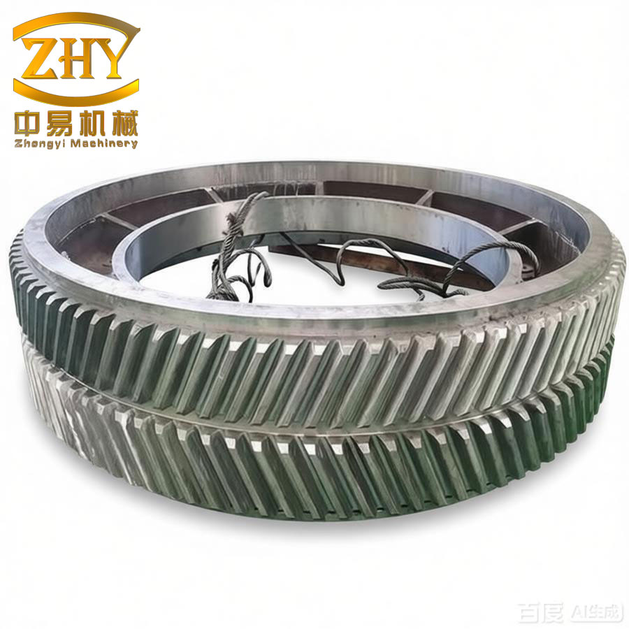
illustrates a typical herringbone gear pair. The time-varying mesh stiffness used in our simulation had a larger fluctuation than realistic values, so the computed displacements are conservatively high. The results are summarized in Table 3.
| Gear | Max Axial Displacement (×10−6 m) |
|---|---|
| Gear 1 | 0.45 |
| Gear 2 | 0.44 |
| Gear 3 | 1.80 |
| Gear 4 | 1.78 |
The axial displacements of gears 1 and 2 are an order of magnitude smaller than those of gears 3 and 4 (0.45 μm vs. 1.80 μm). Gears 3 and 4 exhibit periodic sharp peaks due to the axial floating motion and collisions with the driving gears. The overall magnitude is still in the micrometer range, indicating that in an ideal error-free case, axial vibration is well suppressed.
4.3 Axial Vibration Due to Tooth Profile Error
When a combined tooth profile error e0 = 10 μm is introduced, the axial displacements become negligible compared to the previous excitations. Table 4 lists the maximum values.
| Gear | Max Axial Displacement (×10−7 m) |
|---|---|
| Gear 1 | 0.12 |
| Gear 2 | 0.11 |
| Gear 3 | 0.18 |
| Gear 4 | 0.17 |
These displacements are two orders of magnitude smaller than those caused by helix angle error or time-varying mesh stiffness. Therefore, tooth profile errors have a minor influence on axial vibration of herringbone gears.
5. Discussion
From the numerical results, we observe that the helix angle error is the most dominant excitation for axial vibration. A 0.1° error can produce axial displacements of nearly 5 μm on the driven gears, which is critical for thrust bearing clearance—typically only a few tens of micrometers. The time-varying mesh stiffness also contributes significantly, especially at high speeds where the meshing frequency may excite resonances. The tooth profile error, while important for transmission accuracy, plays a negligible role in axial dynamics.
It is noteworthy that the axial floating of one gear (usually the driven wheel) amplifies the vibration because it allows the unbalanced axial force to translate into displacement without significant constraint. Enhancing the axial stiffness of thrust bearings can reduce these displacements. Our model provides a basis for selecting an optimal stiffness that balances vibration reduction and bearing load capacity.
6. Conclusion
In this paper, we have developed a comprehensive dynamic model for a high-speed herringbone gear transmission and analyzed its axial vibration characteristics under various excitations. The following conclusions are drawn:
- Helix angle error is the primary cause of axial vibration in herringbone gears. Even small deviations (0.1°) lead to axial displacements up to 4.8 μm on the driven gears. Strict control of helix angle accuracy is essential.
- Time-varying mesh stiffness also induces notable axial vibration, particularly on the floating driven gears. Increasing the mesh stiffness (e.g., by optimizing tooth profile or using higher modulus materials) can mitigate this effect.
- Tooth profile errors have a relatively minor impact on axial vibration compared to the other two excitations. Their influence is more significant on transmission error and noise rather than axial dynamics.
- The axial displacement of the driven gear is typically larger than that of the driving gear due to axial floatation. This suggests that thrust bearings supporting the driven shaft require careful stiffness design to limit axial motion.
Our findings provide a theoretical foundation for the design of thrust bearings and vibration reduction strategies in high-power herringbone gear transmissions. Future work will focus on experimental validation and optimization of bearing stiffness to achieve both low vibration and high reliability under varying load conditions.