
Cycloidal gears serve as core functional components in RV reducers. Due to their porous multi-hole structure, deformation occurs during gear hobbing under cutting forces, leading to precision deviations that compromise reducer performance. Predicting cutting forces and deformations during gear hobbing is therefore essential for improving machining accuracy. This study derives cycloidal gear tooth profiles and hob blade equations using the envelope method and gear meshing principles. Finite element analysis (FEA) simulates the gear hobbing process, analyzes cutting forces, and evaluates deformation patterns. Key research contributions include:
Geometric Modeling and Characteristic Analysis
The cycloidal gear tooth profile equation is derived based on the envelope method and gear meshing theory. For a cycloidal gear with base circle radius $r_1 = 38.5 \text{ mm}$, pin gear radius $r_2 = 40 \text{ mm}$, pin tooth radius $r_z = 7 \text{ mm}$, and center distance $e = 1.5 \text{ mm}$, the parametric equations are:
$$X = -\frac{e r_1 \sin \phi_1}{r_2} + R_2 \sin \left( \frac{r_1 + r_2}{r_2} \phi_1 \right) – r_z \sin \gamma$$
$$Y = \frac{e r_1 \cos \phi_1}{r_2} – R_2 \cos \left( \frac{r_1 + r_2}{r_2} \phi_1 \right) + r_z \cos \gamma$$
where $\gamma = \tan^{-1} \left( \frac{r_2 \sin \phi_2}{R_2 – r_z \cos \phi_2} \right)$ and $\phi_2 = \frac{r_1}{r_2} \phi_1$. The hob blade profile is derived using worm gear meshing principles, with key parameters calculated as:
$$p_n = \frac{2 \pi r_a}{Z_1}, \quad d_0 = d – 4e, \quad \sin \gamma_z = \frac{m Z_0}{d_0}$$
where $p_n$ is normal pitch, $d_0$ is pitch diameter, and $\gamma_z$ is helix angle. Hobbing kinematics are modeled via homogeneous coordinate transformations:
$$M_{61} = M_{65} M_{54} M_{43} M_{32} M_{21}$$
representing spatial relationships between workpiece and tool coordinate systems. Undeformed chip geometry analysis reveals thickness variations during cutting cycles:
| Blade Position | Chip Thickness (mm) | Length (mm) |
|---|---|---|
| 1 & 2 | 0.35 | 13.0 |
| 3–6 | 0.15–0.25 | 11.5–12.5 |
| 7 & 8 | 0.30 | 12.8 |
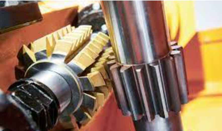
Cutting Force Simulation in Gear Hobbing
A simplified single-tooth FEA model simulates gear hobbing of 25CrMo4 steel using DEFORM-3D. The Johnson-Cook constitutive model governs material behavior:
$$\sigma = \left( A + B \epsilon^n \right) \left( 1 + C \ln \frac{\dot{\epsilon}}{\dot{\epsilon_0}} \right) \left( 1 – T^{*m} \right)$$
with parameters $A = 1200 \text{ MPa}$, $B = 891$, $n = 0.2$, $C = 0.02$, $m = 0.64$. Model validation against experimental gear hobbing data shows strong correlation:
| Speed (rpm) | Feed (mm/r) | Simulated $F_z$ (N) | Experimental $F_z$ (N) | Error (%) |
|---|---|---|---|---|
| 300 | 1.667 | 556.4 | 609.1 | 8.6 |
| 900 | 1.667 | 571.7 | 624.8 | 9.3 |
Cutting forces exhibit distinct temporal patterns during gear hobbing (600 rpm, 0.5 mm/r feed):
Axial force ($F_z$): Peaks at 800 N during stable cutting (2–5 ms) due to maximum shear zone area.
Radial force ($F_r$): Reaches 400 N at 1.6 ms then declines as tool exits.
Tangential force ($F_t$): Peaks at 80 N (4–6 ms) influenced by chip width variations.
Parametric analysis reveals gear hobbing force sensitivity:
$$F_z = 791 + 0.054V_c + 111f_a \quad (R^2 = 0.96)$$
where $V_c$ is cutting speed (rpm) and $f_a$ is axial feed (mm/r). Feed rate dominates force generation, with critical thresholds observed at $f_a = 0.75$ mm/r where forces increase nonlinearly by 35%.
Deformation Analysis in Gear Hobbing
Structural rigidity zones are classified based on hole geometry:
| Zone | Feature | Relative Stiffness |
|---|---|---|
| I | Trapezoidal holes | Weak |
| II | Ribbed sections | Strong |
| III | Circular holes | Medium |
Maximum deformations occur in Zone I during full-cut phase (600 rpm, 0.5 mm/r):
| Hobbing Stage | Deformation (μm) |
|---|---|
| Entry cut | 8.19 |
| Full-cut (mid) | 9.71 |
| Full-cut (end) | 10.47 |
| Exit cut | 9.00 |
Radial ($\Delta R$) and tangential ($\Delta T$) deformations obey:
$$\Delta R = 6.5 + 0.0013V_c + 1.7f_a, \quad \Delta T = 2.1 + 0.0007V_c + 2.9f_a$$
Feed rate contributes 89% to radial deformation variance versus 11% for cutting speed. Critical deformation thresholds occur at $f_a > 0.75$ mm/r where $\Delta R > 8.19$ μm and $\Delta T > 5.67$ μm, exceeding typical RV reducer tolerances of ±3 μm.
Conclusions
1. Undeformed chip thickness varies cyclically during gear hobbing, with Positions 1-2 and 7-8 generating thicker chips (0.30–0.35 mm) than middle positions (0.15–0.25 mm).
2. Cutting forces increase by 9–11% when $V_c$ rises from 300 to 900 rpm and by 35% when $f_a$ exceeds 0.75 mm/r during gear hobbing.
3. Maximum deformation (10.47 μm) occurs in trapezoidal hole zones (Zone I) during full-cut phase, with feed rate contributing 89% to radial error.
4. Optimal gear hobbing parameters for minimal deformation are $V_c ≤ 450$ rpm and $f_a ≤ 0.5$ mm/r, limiting deformations to <8 μm.