This article focuses on the fracture failure analysis of bevel gears. Through a series of experimental methods such as macroscopic fracture morphology observation, elemental spectroscopic composition analysis, and metallographic microstructure analysis, the root causes of bevel gear fractures are explored. It also provides detailed solutions and improvement measures to enhance the performance and service life of bevel gears, offering valuable references for related industries.
1. Introduction
Bevel gears play a crucial role in the automotive transmission system, especially in the main reducer. They are responsible for reducing speed, increasing torque, and changing the direction of torque rotation. Specifically, the active bevel gear is a key component that controls the vehicle’s steering system, adjusts the linear speed of the inner and outer wheels, and ensures smooth turning of the vehicle. However, when bevel gears fail prematurely, it can lead to serious safety issues and economic losses. Therefore, a comprehensive understanding of the causes and solutions for bevel gear fractures is of great significance.
The processing technology of bevel gears generally includes steps such as blanking, hot forging, normalizing (pre – heat treatment), rough machining, finish machining, carburizing and quenching, tempering, and precision grinding. Pre – heat treatment is essential as it can eliminate the uneven distribution of austenite, relieve the stress generated during forging, reduce the risk of cracks, and improve the machinability, laying a solid foundation for the final quenching and tempering heat treatment.
2. Failure Case Introduction
In this study, the bevel gear of the automotive main reducer failed abnormally before reaching its normal service life. The design standards for this gear require an effective surface hardening layer depth of 0.8 – 1.1mm, a surface hardness of 58 – 64HRC, and a matrix hardness of 32 – 48HRC. To identify the root cause of the failure and provide theoretical guidance for subsequent production, a series of in – depth analysis and testing were carried out.
3. Analysis and Testing Methods
3.1 Macroscopic Observation
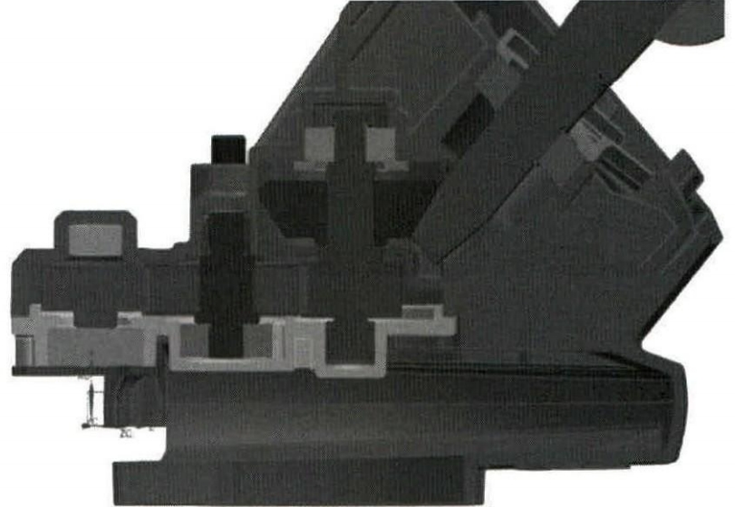
The first step in the failure analysis is to conduct a macroscopic observation of the broken bevel gear. As shown in Figure 1, most of the teeth of the active bevel gear are broken, and macroscopic cracks can be observed at the roots of the unbroken teeth. By examining the fracture surface, distinct beach – mark – like crack propagation traces can be found on two of the broken teeth, indicating that the failure belongs to low – cycle fatigue fracture.
| Observation Item | Result |
|---|---|
| Tooth Fracture Condition | Most teeth broken, cracks at roots of unbroken teeth |
| Crack Propagation Traces | Beach – mark – like, indicating low – cycle fatigue fracture |
3.2 Chemical Composition Analysis
The chemical composition of the gear tooth surface was determined using a direct – reading spectrometer. The gear is made of 20CrMnTiH steel, and the analysis results of its chemical elements are presented in Table 1. It can be seen that all the element contents meet the requirements of GB/T 3077 – 2015 “Alloy Structure Steel Standard”.
| Element | Content (Mass Fraction, %) | Standard Requirement |
|---|---|---|
| C | 0.22 | – |
| Si | 0.33 | – |
| Mn | 0.65 | – |
| P | 0.015 | – |
| S | 0.016 | – |
| Cr | 1.06 | – |
| Ti | 0.056 – 0.058 | – |
| Cu | 0.029 | – |
| Ni | – | – |
3.3 Hardness Test
Samples were taken from the remaining tooth surface and the inner part of the matrix to measure the Rockwell hardness of each part. The test results are shown in Table 2. The matrix hardness is close to the lower limit of the design requirement, while the average surface hardness of the gear is lower than the design requirement, and there is significant hardness unevenness, with a large numerical gradient. This indicates the presence of abnormal structures in the surface layer.
| Test Item | Measurement 1 (HRC) | Measurement 2 (HRC) | Measurement 4 (HRC) | Average Value (HRC) | Design Requirement (HRC) |
|---|---|---|---|---|---|
| Surface | 53.3 | 58.9 | 54.1 | 56.4 | 58 – 64 |
| Matrix | 32.7 | 32.3 | 32.1 | 32.6 | 32 – 48 |
3.4 Determination of Surface Effective Carburized Hardening Layer Depth
Samples were taken at 3 points on the surface layer, and the average value of the surface effective hardening layer depth of the gear was measured using a micro – Vickers hardness tester. The result is 0.86mm (the requirement is 0.8 – 1.1mm), and the hardness limit is 550HV1. According to the standard (GB/T 9450 – 2005 “Determination and Verification of the Depth of the Carburized and Quenched Hardening Layer of Steel Parts”), the measurement result meets the design requirements.
| Sampling Location | Hardening Layer Depth (mm) | Average Value (mm) | Design Requirement (mm) |
|---|---|---|---|
| Point 1 | – | 0.86 | 0.8 – 1.1 |
| Point 2 | – | ||
| Point 3 | – |
3.5 Metallographic Analysis
Metallographic specimens were prepared at the broken teeth. After rough grinding, fine grinding, and polishing, non – metallic inclusions were observed under a metallographic microscope. Non – metallic inclusions can disrupt the continuity of the matrix structure, change the distribution of material forces, and cause stress concentration. However, no obvious non – metallic inclusions were found near the fracture and in the matrix, and only a small amount of spherical oxides, all below grade 1, were present, as shown in Figure 2. Therefore, they are not the main cause of gear fracture.
The polished specimens were etched with 4% nitric acid alcohol, washed, dried, and then observed microscopically. The microstructure of the carburized hardening layer on the surface of the unbroken gear is fine – needle martensite + a small amount of retained austenite, which is a normal product after quenching, as shown in Figure 3. The microstructure of the core is lath – shaped bainite + sorbite. Although this structure can reduce the bending strength of the gear, since it is located in the core and is not the main stress – bearing part, its impact on gear fracture is relatively small.
However, a network of non – martensitic structures was found on the surface of the broken gear root, as shown in Figure 4. The depth of this non – martensitic structure is approximately 0.04mm. According to the national automotive industry standard QC/T 262 – 1999 “Metallographic Inspection of Carburized Gears for Automobiles”, the maximum depth of the non – martensitic structure on the gear surface should not exceed 0.02mm. The presence of a deeper non – martensitic structure can seriously reduce the surface hardness, wear resistance, and fatigue limit of the gear.
4. Discussion of Test Results
The presence of a relatively deep non – martensitic structure on the gear surface, which penetrates along the original austenite grain boundaries in a network pattern, is the main cause of gear failure. This non – martensitic structure severely weakens the surface and grain boundary strength of the gear, reduces its wear resistance and fatigue life. During the service process of the gear, the non – martensitic structure causes uneven surface hardness, resulting in stress concentration and the generation of fatigue crack sources. The continuous expansion of multiple crack sources eventually leads to gear fracture.
5. Improvement Measures and Effects
5.1 Improvement Measures
There are two main ways to solve the problem of non – martensitic structure generation. One is to reduce elements that are preferentially selectively oxidized when selecting materials. The order of elements being preferentially oxidized is However, in the current situation of the domestic gear industry, the second method, reducing the oxidizing components in the carburizing atmosphere (such as reducing the oxygen partial pressure), is more acceptable to manufacturers.
Specific measures include: (1) Since the generation of non – martensitic structures indicates the presence of an oxidizing atmosphere in the heat treatment furnace, it is necessary to improve the cleanliness of the carburizing atmosphere in the furnace. This can be achieved by strictly controlling the tightness of the heat treatment furnace and appropriately extending the exhaust time of the furnace to make the carburizing atmosphere in the furnace purer. (2) The overall surface hardness of the failed gears is on the low side. Appropriately increasing the surface hardness can improve the tooth surface contact fatigue strength. To achieve this, it is necessary to ensure the cleanliness of the workpiece surface before carburizing to improve the surface hardness and uniformity. (3) During the carburizing process, due to the high carbon potential at the tooth root and the slower cooling rate compared to other parts, non – martensitic structures are likely to form at the tooth root. Therefore, it is necessary to appropriately increase the quenching cooling rate of the gear to reduce or eliminate this defect.
5.2 Effects
Based on the improvement suggestions, the heat treatment process was adjusted, including the oxidation atmosphere and quenching cooling process. Sampling and observation of a new batch of gears showed no obvious network – shaped surface non – martensitic structures. Although completely eliminating this structure requires high requirements for material quality and heat treatment processes, the process adjustment has significantly improved the surface structure defects of the gears. This indicates that the analysis method in this article is highly effective and can provide certain guidance for gear processing technology.
6. Conclusion
In conclusion, through a series of analysis and testing methods, it is determined that the main reason for the fracture failure of the bevel gear is the presence of a deep non – martensitic structure on the gear surface. By taking corresponding improvement measures, such as optimizing the heat treatment process, the surface structure of the gear can be effectively improved, and the performance and service life of the gear can be enhanced. This research provides valuable reference for the design, production, and quality control of bevel gears in related industries, helping to improve the overall reliability and safety of mechanical transmission systems. Future research can further explore more advanced detection methods and optimization strategies to continuously improve the quality of bevel gears.