
Regardless of the deformation, the meshing point of a pair of helical gears at any time should be on the theoretical meshing line. However, in practical work, errors and load-bearing deformation are inevitable. The resultant pitch error of helical gear meshing caused by it makes the pitch of driving and driven wheels no longer equal. When entering and exiting meshing, the meshing point deviates from the theoretical meshing line, resulting in geometric interference at the contact position, forming meshing in and meshing out impact, which is manifested in the sudden change of helical gear transmission ratio and meshing force, resulting in vibration excitation.
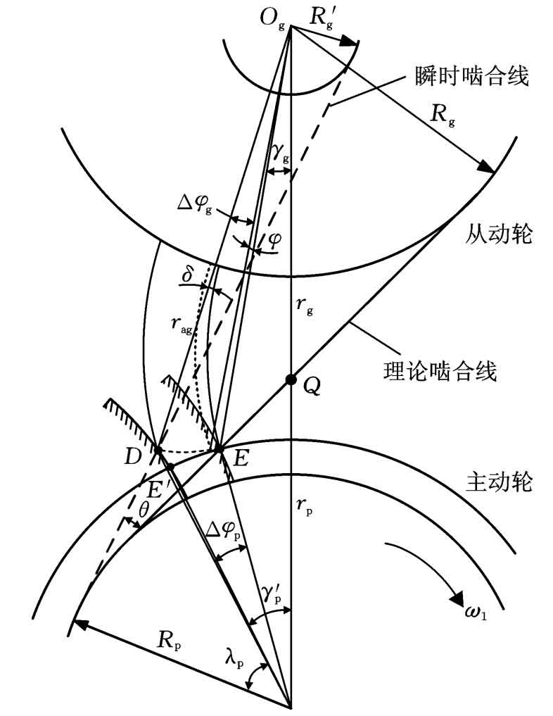
The formation mechanism of meshing impact and meshing impact is the same, but the impact of meshing impact on the system is significantly higher than that of meshing impact on the system. Therefore, only taking meshing impact as an example, its impact on system vibration is analyzed. The formation principle of meshing impact is shown in Figure 1.
In Figure 1, OP is the center of the driving wheel, og is the center of the driven wheel, q is the node, D is the starting point of off-line engagement, e is the starting point of normal engagement, and E ‘is the reverse point of point E, δ Is the comprehensive deformation of the meshing tooth pair (obtained by LTCA). In Δ Opdog and Δ In Qdog, according to the geometric relationship:
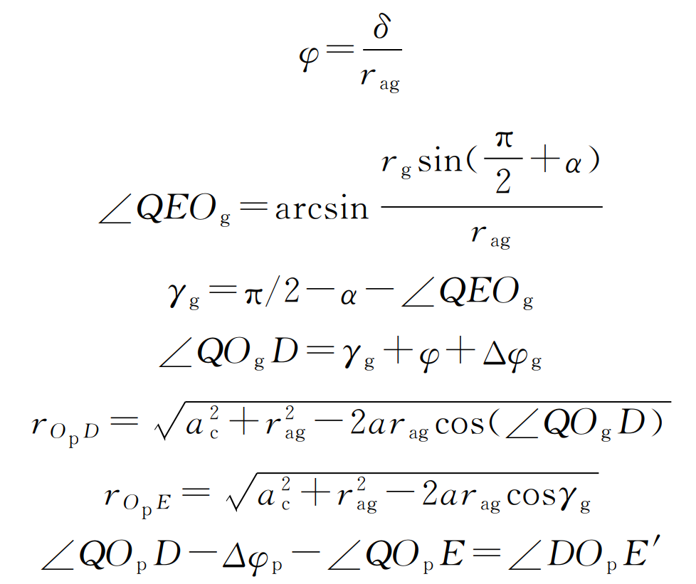
Where, rag is the radius of the top circle of the driven gear; RP and RG are the base circle radius of the main driven wheel respectively; RP and RG are the pitch radius of the main driven wheel respectively; AC is the gear center distance; I is the helical gear transmission ratio; α Is the pressure angle of the dividing circle.
The rotation angle of driving wheel from meshing point to normal meshing point can be obtained by simultaneous formula Δφ p. So as to obtain the impact time Δ T is:
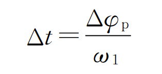
Where, ω 1 is the angular speed of driving wheel.
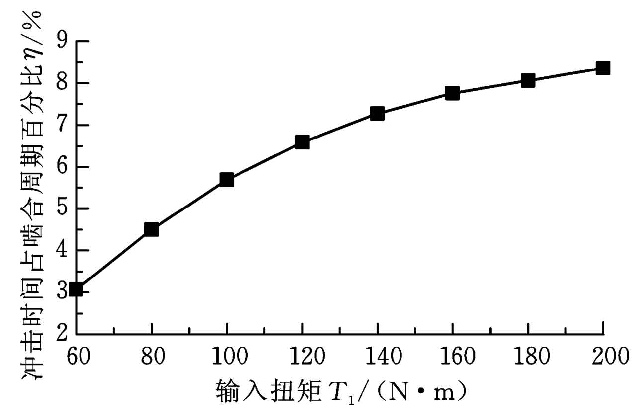
It is not difficult to find that once the helical gear size parameters are determined, the meshing impact time Δ Tcomprehensive deformation of meshing tooth pairs only δ Relevant (other factors change through influence δ And influence Δ t)。 The load torque affects the comprehensive deformation of the meshing tooth pair δ Figure 2 shows the change of meshing impact time as a percentage of meshing cycle under different loads. It can be seen from Figure 2 that the percentage of meshing impact time in the meshing cycle is between 3% and 8.4%, and it increases with the increase of load torque, but its increasing speed slows down. This is because the contact area of the tooth surface increases with the increase of torque, and the bearing capacity of the tooth surface increases, resulting in comprehensive deformation δ The increase of slowed down.
According to the impact dynamics theory and considering the influence of coincidence degree on meshing impact, the amplitude expression of meshing impact force is:
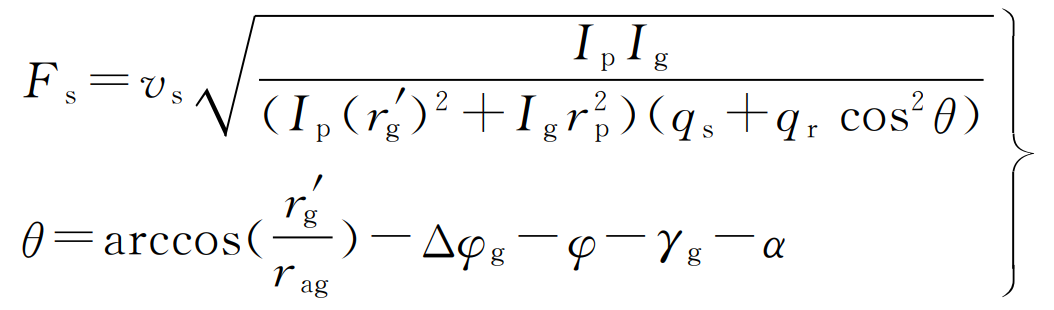
Where, vs is the impact velocity of the off-line meshing point; QS is the flexibility of single tooth pair meshing into point D outside the line; QR is the comprehensive flexibility of other tooth pairs except the impact tooth at the time of meshing; θ Is the angle between the instantaneous meshing line and the theoretical meshing line; IP and Ig are the rotational inertia of the main driven wheel respectively; R ′ G is the instantaneous base circle radius of the outer meshing of the driven wheel line.
In the formula, QS and QR can be obtained by multiplying the comprehensive meshing stiffness of helical gear teeth obtained by LTCA by their respective load distribution coefficients.
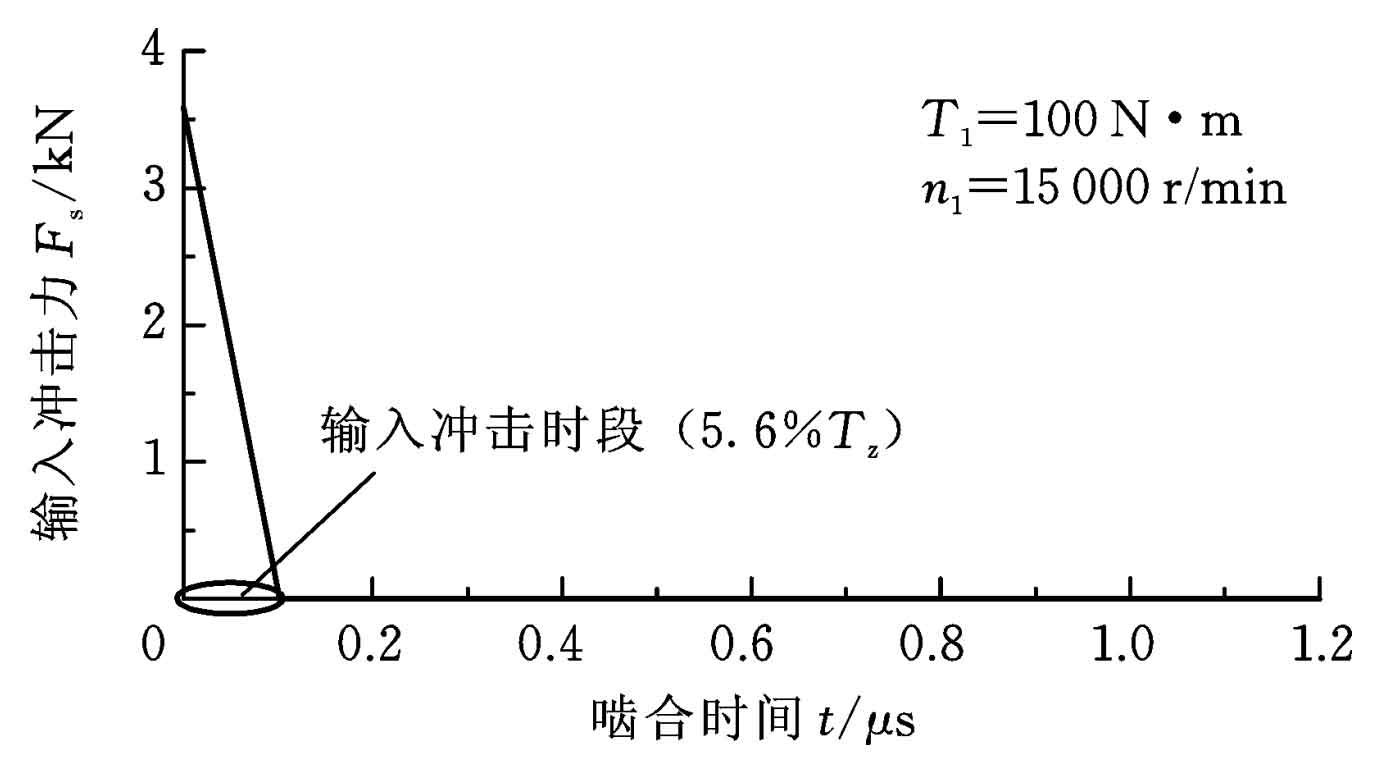
Because the meshing impact time of helical gears is very short, the meshing impact force is often simplified as a sawtooth wave function. According to the above analysis, the meshing impact force curve shown in Figure 3 can be obtained, where TZ represents the meshing cycle, T1 and N1 are the input torque and speed respectively.