Tool position calculation is to calculate the position and attitude of the tool relative to the workpiece (referred to as tool position) according to the machining adjustment parameters of the gear cutting machine tool. In the five coordinate machining of spiral bevel gear, the geometric meshing relationship between cutter head and tooth surface is very complex. It is also the key of five coordinate NC machining and programming of spiral bevel gear. The tool position calculation method of five coordinate NC machining of spiral bevel gear with disk milling cutter is analyzed theoretically.
In order to find the tool path in the machine tool coordinate system, the key is to convert the geometric parameters on the tooth surface of spiral bevel gear into tool position data. The CL tool position is calculated based on the tooth surface model and tool contact point parameters.
Let the radius of the milling cutter head be R0, the cutter tip distance be w, and the tooth profile angle be α 0. The control mode of the cutter axis relative to the surface is shown in Figure 1.
Where, n is the unit normal vector of the cutting point on the surface, t is the unit shear loss along the feed direction at the cutting point, v = NXT, {n, t, V} is the local coordinate system of the surface at the cutting point. The control mode consists of two angles of tool axis vector I in local coordinate system α,γ To decide. α It is called leading or lagging angle, which is the angle between the cutter axis and the plane perpendicular to the feed direction: γ It is called the inclination angle, which is the included angle between the cutter axis and the normal vector of the surface.
The tool position in spiral bevel gear NC machining refers to the coordinate value and tool axis vector of the center point of the tool tip plane of the milling cutter head, as shown in Figure 2.
According to the geometric relationship shown in Figure 2, it can be obtained that:

Where a, γ, B2 can be determined by the normal curvature in the tooth length direction and the normal curvature in the tooth height direction, that is, the normal curvature in the tooth length direction and the normal curvature in the tooth height direction are met by the cutter head radius and the cutter shaft inclination respectively.
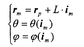
In Figure 2, set M as the swing center, and the length from the swing center to the tool center P is L. if the swing center is taken as the translational reference point of the machine tool, set the motion of the two swing shafts of the machine tool as θ and φ, Then the ideal tool path of the machine tool is:

When the cutter head cuts along the contact path, the gear tooth surface can be enveloped through the deflection of the cutter head axis and the movement in the axis direction, so as to process the spiral bevel gear on the five coordinate NC machine tool.


