
Based on the gear meshing principle and the gear cutting principle of spiral bevel gear large wheel, the tooth surface equation RG of spiral bevel gear large wheel can be established. Because the tooth surface of spiral bevel gear is a spatial complex surface, in order to measure the tooth profile error of the actual tooth surface relative to the theoretical design tooth surface, it is necessary to discretize the theoretical tooth surface, and calculate the spatial positioning and normal vector of each discrete point of the tooth surface in the gear coordinate system based on the tooth surface equation of the large gear.
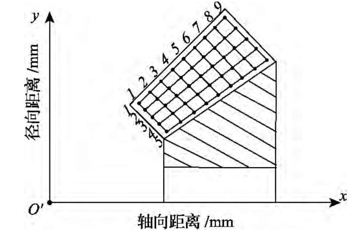
According to AGMA 2009-b01 standard, grid planning is carried out in the rotating projection plane of the tooth surface of the gear tooth. 9 columns are taken along the tooth length direction of the gear tooth and 5 rows are taken along the tooth height direction of the gear tooth, with a total of 45 discrete points, as shown in the figure. According to the basic geometric parameters of the big wheel and the shrinkage of the grid around the tooth surface, the coordinates (x (I, J), y (I, J)) (I = 1 ~ 9, j = 1 ~ 5) of each discrete point in the coordinate system with the design intersection o ‘of the gear pair as the origin can be calculated.
Let the distance from any discrete point on the tooth surface to the gear axis P (x-axis in the figure) be y, and the distance from the gear axis to the design intersection o ‘be X. it can be seen from the figure:
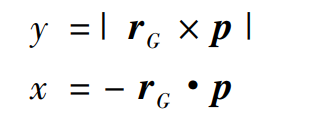
For large wheels processed by generating method, X and y are generating angles Δ Q2 and cutter head phase angle θ Function of 2; For the large wheel machined by forming method, X and y are the cutter head phase angle θ 2 as a function of the distance S2 to the apex of the tool tip. Given Δ q2、 θ 2 or θ 2. S2, X and y can be calculated according to equations (1) and (2). If the coordinates of discrete points (x (I, J), y (I, J)) are given, the corresponding coordinates can be calculated by Newton’s binary iterative method Δ q2、 θ 2 or θ 2. S2, and then the spatial coordinates and normal vectors of each discrete point on the theoretical tooth surface of the large wheel in the gear coordinate system can be obtained.