
The machining method of the eccentric modified gear generated by the modification method is the same as that of elliptical and non-circular gears. The machining essence is that the rack tool pitch line is tangent to the eccentric gear pitch curve and pure rolling. A modification amount MX must be superimposed in the vertical direction of the rack tool, so as to envelope the involute tooth profile of the eccentric modified gear.
The number of teeth of the eccentric gear is designed as an odd number. In the initial position, one end of the long shaft of the driving eccentric gear is a tooth, and the conjugate eccentric displacement gear corresponds to a tooth slot. During computer simulation processing, wheel I rotates clockwise around the axis and wheel II rotates counterclockwise around the axis. One side of the rack tool translates downward, and the downward translation distance is the arc length corresponding to the rotation angle of the eccentric gear; One side horizontally translates and rotates at a certain angle to ensure that the rack pitch line is tangent to the two curves.
Assuming that the tooth blank of the eccentric modification gear is fixed and the rack tool pitch line makes pure rolling around the tooth blank pitch curve, figure 1 shows the position relationship between the rack tool and the tooth blank of the eccentric modification gear.
Polar coordinate equation of pitch curve of eccentric gear II:
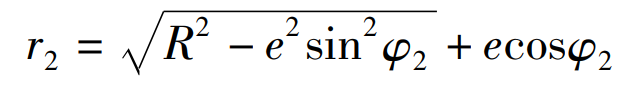
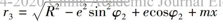
Then the polar coordinate equation of the pitch curve of the eccentric modified gear is:
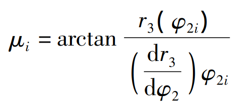
When it is set at the starting position, the pitch line of the rack tool is tangent to the pitch curve of the eccentric gear blank at point A. when the pitch line of the rack tool rolls purely to the polar angle along the pitch curve of the eccentric gear φ 2I, tangent to the gear blank pitch curve at point B, and the included angle between the pitch line and the diameter vector ob μ I is:
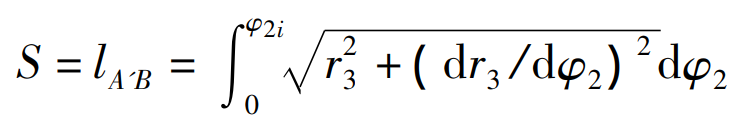
At this time, point a moves to point a ‘, and the arc length s between AB is equal to the distance between a’B, that is:
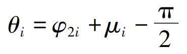
Angle of rack θ I is:
When the rack rotates for one cycle, the pitch curve of workpiece eccentric gear II can be enveloped according to the formula.
On the basis that the rack pitch line envelops the workpiece eccentric gear pitch curve, the rack tooth profile envelops the involute tooth profile of the eccentric gear. The tool rack is composed of several teeth, each tooth can be represented by four vertices (Fig. 1), the first tooth is composed of four vertices 1, 2, 3 and 4, and the other teeth are obtained by the coordinate translation of the first tooth. When the gear blank angular displacement φ 2 when the corresponding arc length s is greater than a pitch P or an integral multiple of the pitch, the coordinate y vector of the rack tool moves forward an integral multiple of the pitch P to ensure that there are enough rack teeth to envelop the eccentric gear each time. In the rack coordinate system, the mathematical model of the tool rack is expressed in matrix form as follows:
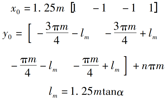
Where n — number of teeth of rack
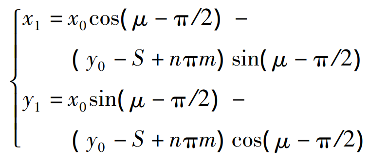
Turn the rack to the direction tangent to the pitch curve of the gear blank, and the mathematical model is:
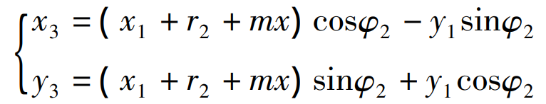
Put the rack to the pure rolling position tangent to the gear blank, and then offset MX for displacement, the mathematical model is:
With φ 2 constantly changing, the rack rotates for one cycle, enveloping the tooth profile of the eccentric modification gear, as shown in Figure 2.
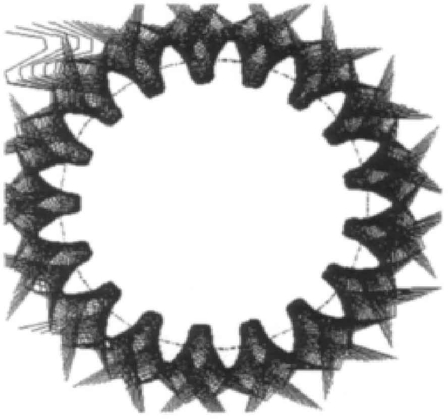
The involute tooth profile is formed by connecting the intersection of the envelope, the tooth top curve of the eccentric modification gear is a normal isometric line with a distance of MH * a from the pitch curve, and the tooth root transition curve is formed by enveloping the vertex of the rack tooth top segment. Therefore, the tooth root transition curves of all teeth of the eccentric gear, the involute tooth profile and the tooth profile feature points of the tooth top curve are connected into a complete tooth profile in sequence.