Mechanical transmission devices are developing towards high power density and high integration. Therefore, reducing the volume of gears and improving the transmission ratio and efficiency of single-stage gears are crucial. A study was conducted on the dynamics of low tooth involute gears, and the calculation method for the root cutting radius of low tooth involute gears was improved. The CNC machining of low tooth involute gears was also studied, and the contact strength formula was modified based on the characteristics of external meshing gear transmission at nodes. It was found that the meshing method of external meshing gears after using nodes can improve the contact strength of gear pairs. An analysis was conducted on the causes of external meshing of nodes, and the impact of external meshing on gear strength was summarized. Outside the node The coupling dynamics of the meshing planetary gear system were analyzed and experimentally verified. A dynamic model of the single-stage gear transmission system with external meshing nodes was established and solved. The time-domain dynamic response and phase diagram of the system were obtained, and the dynamic characteristics of the system were analyzed. In response to the shortcomings of the average friction coefficient calculation method in the existing adhesive bearing capacity calculation methods,gear the meshing stiffness and bearing capacity of the bevel gear were improved by designing the tooth surface topology structure, reducing its vibration and noise. The geometric design of high reduction ratio hypoid gears was studied, and the feasibility of the design method for hypoid gears with equal height teeth and high reduction ratio was verified through cutting experiments. Three dimensional simulation, machining simulation, and experimental research were conducted on high reduction ratio hyperbolic gears. The external meshing of nodes has been extensively studied in the design of cylindrical gears. gear This is the first time that the design of bevel gears is described as external meshing of pitch cones. The gear pair with a tooth ratio of 4:41 adopts a comprehensive displacement and pitch cone external meshing design. The circular arc cutting edge of the small wheel teeth was modified, and the machining parameters of the small wheel were optimized and simulated.
The difference in gear ratio is significant, and the volume and strength of the large and small wheels differ greatly. Therefore, a design method of comprehensive displacement and external meshing of the pitch cone is adopted to balance the strength of the large and small wheels, improve the bearing capacity of the gear pair, and at the same time,gear the use of external meshing of the pitch cone also has the advantage of adjusting the sliding of the tooth surface and the frictional force without reversing direction. Based on the processing parameters of the small wheel, an accurate 3D model of the small wheel is established and assembled with the large wheel. Dynamic simulation is carried out in UG to observe the instantaneous contact state of the gear pair, gear the contact path and instantaneous contact situation of the gear teeth from entering mesh to exiting mesh. The instantaneous contact area is ideally elliptical.
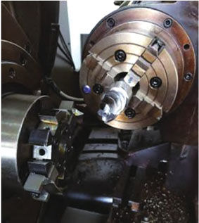
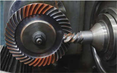
The gear cutting test is conducted on the GH-35 machine tool. Due to the different processing methods used for the large and small wheels, it is necessary to combine specific processing methods, consider specific cutting processes and steps, and develop CNC machining programs. Convert the pre-processing parameters into adjustment parameters for GH-35 machine tool. After completing the gear cutting test, the rolling detection of the matching teeth of the small and large wheels is based on the machining parameters of the small wheel. An accurate 3D model of the small wheel is established and assembled with the large wheel. Dynamic simulation is carried out in UG to observe the instantaneous contact state of the gear pair, gear the contact path and instantaneous contact situation of the teeth from entering meshing to exiting meshing. The instantaneous contact area is ideally elliptical.
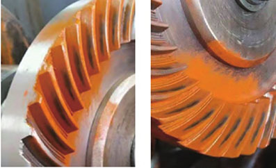
After completing the gear cutting test, conduct a rolling inspection of the matching teeth of the large and small wheels. It can be observed that there is no distortion in the tooth tips of the large and small wheels. The tooth surface contact spots obtained by rolling inspection after several tooth matching and contact area adjustments during the gear cutting process. gear The contact imprint is elliptical, with an inner diagonal shape and no tooth tip contact, gear and the simulated spot trend is consistent.
The tooth surface contact spots obtained by rolling inspection after several tooth matching and contact area adjustments during the gear cutting process. The contact imprint is elliptical, gear with an inner diagonal shape and no tooth tip contact, and the simulated spot trend is consistent.
A geometric design method for the involute bevel gear with fewer teeth is proposed, which integrates displacement and external meshing of nodes. Taking a gear pair with a tooth ratio of 4:41 as an example, relevant geometric parameter design calculations are carried out. gear The method of using a disc cutter to modify the curvature of the small wheel tooth surface has been achieved; Based on the surface synthesis method, the machining parameters of small wheels were optimized and solved; Constructed an easy off differential surface for the small wheel and simulated the tooth contact performance. A CNC cutting program was developed in the article, and the cutting test of a gear pair with a tooth ratio of 4:41 was completed;gear Rolling inspection was conducted on the contact performance of the tooth surface, and the contact spots on the tooth surface were good, verifying the feasibility of the geometric design of the low tooth number high reduction ratio bevel gear and the machining method of the cutter head modification.


