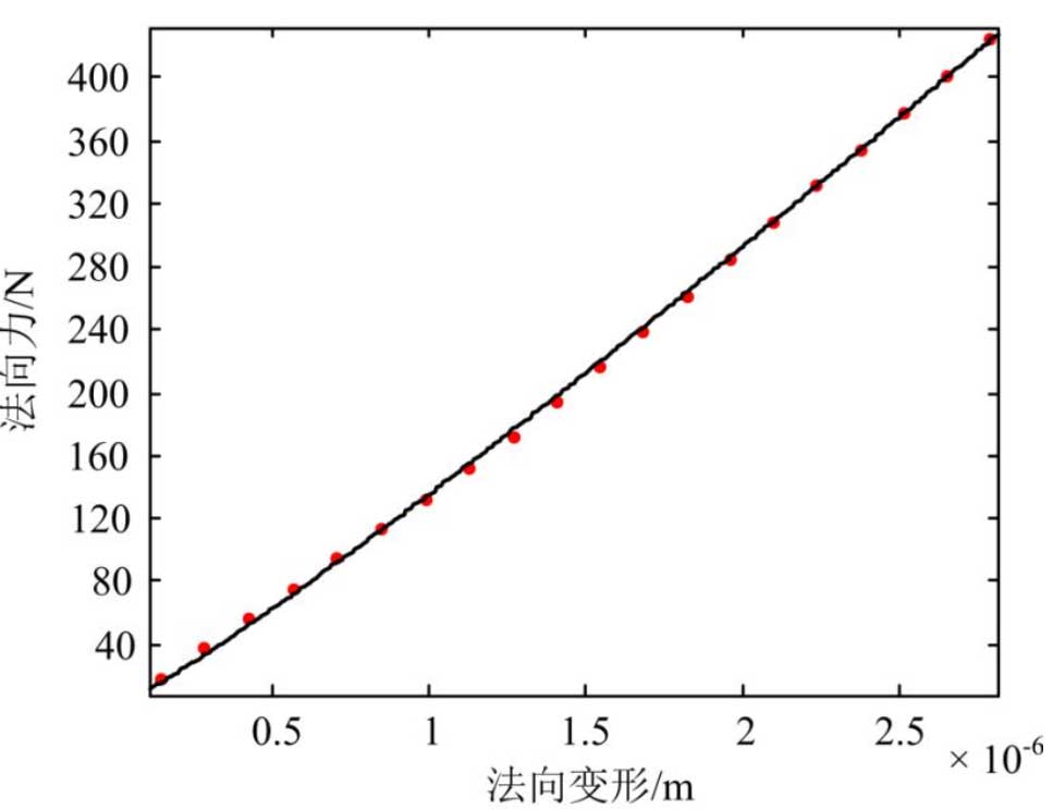
The meshing stiffness of the rodent point can be calculated by LTCA. The basic idea is to increase the load torque of the gear pair according to the given step and obtain the normal deformation of the rodent point under each load torque. At the same time, through the load distribution coefficient and the total normal force at the rodent point, the normal force at the rodent point under each load torque can be obtained, thus a series of normal forces at the rodent point can be obtained.Finally, the relation curve between normal force and normal deformation is obtained by fitting as shown in Figure 6. The relation is FN = Ks Delta n, where Ks is the meshing rigidity of the meshing point and N is the deformation coefficient under static state.
In the geometric contact analysis and calculation of the teeth, the large and small wheel rotation angles at the theoretical engagement position can be obtained. According to the calculation in Section 2, the angle of rotation of the large wheel at the new position can be obtained. Through the contact analysis of the small gear tooth surface and the large gear tooth surface at the new position, the initial contact point (the engagement point) of the large and small wheel teeth at the engagement can be obtained under the fixed coordinate system.Position vectors, as well as normal vectors, are used to obtain the relative speed of large and small wheels at the rodent point, i.e. impact speed.
v⇀f(12)=[(w⇀f(1)−w⇀f(2))]×r⇀f(1)−E⇀f×w⇀f(2)
Where v_f (12) is the relative speed of large and small wheels at the rodent point in the fixed coordinate system, w_f (1) and w_f (2) are the angular velocity of large and small wheels in the fixed coordinate system respectively, r_f (1) is the position vector of the rodent point in the fixed coordinate system, and E_f is the vector from the origin of the fixed coordinate system to the origin of the large wheel coordinate system.