
As a key component of gear transmission systems, straight bevel gear is widely used in fields such as automobiles, precision machine tools, and aerospace. The time-varying mesh stiffness is an important basis for evaluating the performance of straight bevel gear transmission, and accurate calculation of its time-varying mesh stiffness is an important prerequisite for ensuring the stability of straight bevel gear transmission performance. Therefore, it is of great significance to efficiently and accurately calculate the time-varying mesh stiffness of straight bevel gear.
A large amount of research has been conducted by domestic and foreign scholars on the calculation of time-varying meshing stiffness of gears. Among them, there has been more research on cylindrical gears, and the problem of calculating their meshing stiffness has been basically solved. However, there is relatively little research on the time-varying mesh stiffness of spatial straight bevel gear, and most scholars use finite element methods to calculate it. Li Jianfeng et al. used the finite element method to analyze the tooth deformation and instantaneous meshing stiffness of a straight bevel gear with multiple teeth simultaneously meshing. Chen Xia et al. established a finite element contact analysis model for the meshing of straight bevel gear pairs using finite element software, and analyzed the quasi-static meshing state of straight bevel gear pairs. In addition, some scholars use traditional analytical methods for calculations. Elkholy et al. proposed a calculation method for calculating the tooth load and stress of spur bevel gear, and verified the accuracy of this method through experiments. Chen Siyu et al. established a mesh stiffness model for micro segment straight bevel gear based on energy equivalence, and calculated the single tooth mesh stiffness using the integration method.
Analysis shows that although the finite element method has high calculation accuracy, the calculation time is long and the calculation efficiency is limited by many factors; Although traditional analytical calculation methods have a short calculation time, they cannot consider the coupling effect between tooth pairs, which can lead to significant errors in calculating the stiffness of multi tooth meshing. In response to the above issues, ZHY Gear combines the advantages of finite element method and analytical method to propose a slice calculation method for meshing stiffness of straight bevel gear that considers tooth pair coupling. We calculated and analyzed the meshing stiffness, angular displacement of each thin plate center point, and load distribution of straight bevel gear under assembly error conditions, and compared them with finite element calculation results to verify the accuracy of the method proposed in this paper.
1. Calculation model for meshing stiffness of straight bevel gear
1.1 Straight bevel gear slice model
Considering the three-dimensional spatial structure and meshing characteristics of straight bevel gear, the teeth of the straight bevel gear are discretized along the tooth width direction using a back cone, and the wheel body is discretized along the circular plane of the axis direction, forming a series of thin slice straight bevel gear with equal tooth width. Based on the principle of back cone equivalence, the large end back cone of each thin bevel gear is unfolded. When the width of the thin plate is small enough, the straight bevel gear is equivalent to a series of teeth meshing of a series of straight cylindrical gears with the same number of teeth (but different sizes). Figure 1 shows a sliced model of straight bevel gear.
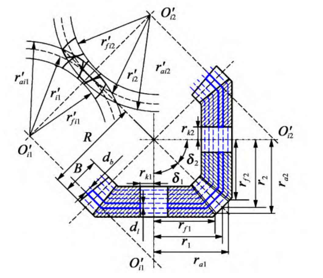
In Figure 1, the teeth of the straight bevel gear are divided into a series of sufficiently small tooth flakes along the tooth width direction, where db is the tooth width of the flakes; Rj, rfj, and raj (j=1,2, respectively representing the driving gear and driven gear, the same below) are the indexing radius, tooth tip radius, and tooth root radius of straight bevel gear, respectively; δ j. B, R, and rkj respectively represent the bevel angle, tooth width, outer cone distance, and shaft hole radius of straight bevel gear.
Based on the principle of back cone equivalence, the large end back cone of the thin plate gear teeth is unfolded, and the i-th thin plate equivalent tooth number zvj, equivalent indexing circle radius r’ij, equivalent tooth top circle radius r’aij, and equivalent tooth root circle radius r’fij can be expressed as follows:
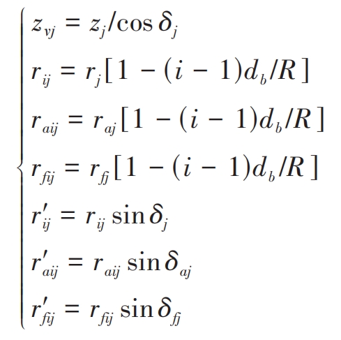
In the formula, i is the serial number of the thin film, i=1, 2,…, n; Z is the number of teeth; δ A and δ F represents the tooth tip angle and tooth root angle of straight bevel gear, respectively.
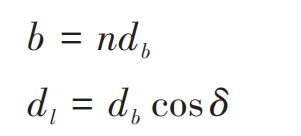
In addition, the thin section of the straight bevel gear wheel body is divided into a series of small enough width wheel body thin sections along the vertical axis direction circular plane. The relationship between the width dl of the thin plate wheel body, the width db of the teeth, the width b of the teeth, and the number of thin plates n can be expressed as:
1.2 Calculation of sheet mesh stiffness
Each thin plate can be approximated as a spur gear, while a straight bevel gear can be approximated as several spur gears in parallel. The stiffness of the thin plates participating in meshing at each instantaneous moment is obtained, and the total meshing stiffness of each meshing position can be obtained by accumulating.
Under external loads, the equivalent meshing stiffness of straight bevel gear caused by tooth deformation includes Hertz contact stiffness, bending stiffness, shear stiffness, and radial compression stiffness; In addition, there is also the equivalent meshing stiffness of straight bevel gear caused by wheel deformation, which is the wheel stiffness. Therefore, the single tooth linear meshing stiffness kdli corresponding to the thin film i can be expressed as:
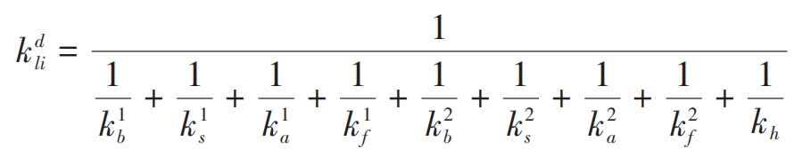
In the formula, kh, kb, ks, ka, and kf are the Hertz contact stiffness, bending stiffness, shear stiffness, radial compression stiffness, and wheel stiffness, respectively. The Hertz contact stiffness can be calculated by equation (10) in reference, the wheel stiffness can be calculated by equation (17) in reference , and the bending stiffness, shear stiffness, and radial compression stiffness can be calculated by equation (2) in reference (26), (2 30), (2 32) Calculation}; Superscripts 1 and 2 represent the driving gear and the driven gear, respectively.
The traditional analytical method for calculating the stiffness of multi tooth meshing is obtained by adding the stiffness of individual tooth pairs, which results in significant calculation errors. This is because traditional analytical methods only consider the case of single tooth meshing when calculating the stiffness of the wheel body, ignoring the coupling effect between tooth pairs. Therefore, this article introduces a wheel body stiffness correction coefficient in the calculation of double tooth meshing stiffness, and expresses the double tooth linear meshing stiffness ksli as:
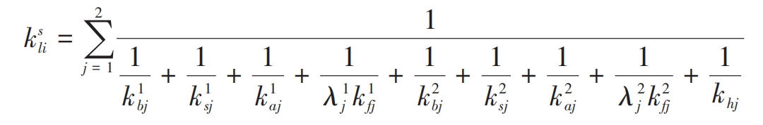
In the formula, j represents the meshing tooth pair; λ 1j λ 2j are the stiffness correction coefficients for the driving and driven wheel bodies, which will be applied in the 1st Determined in Section 3.
In addition, time-varying mesh stiffness can also be evaluated by torsional mesh stiffness. According to the relationship between linear meshing stiffness and torsional meshing stiffness, the torsional meshing stiffness of straight bevel gear can be expressed as:
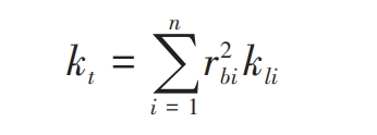
In the formula, rbi is the radius of the base circle corresponding to the thin film i.
1.3 Calculation of stiffness correction coefficient for wheel bodies
Considering the three-dimensional spatial structure of straight bevel gear, establish three-dimensional finite element models of each thin slice straight bevel gear in the finite element software Ansys. Figure 2 shows the finite element model of the thin slice i of straight bevel gear.
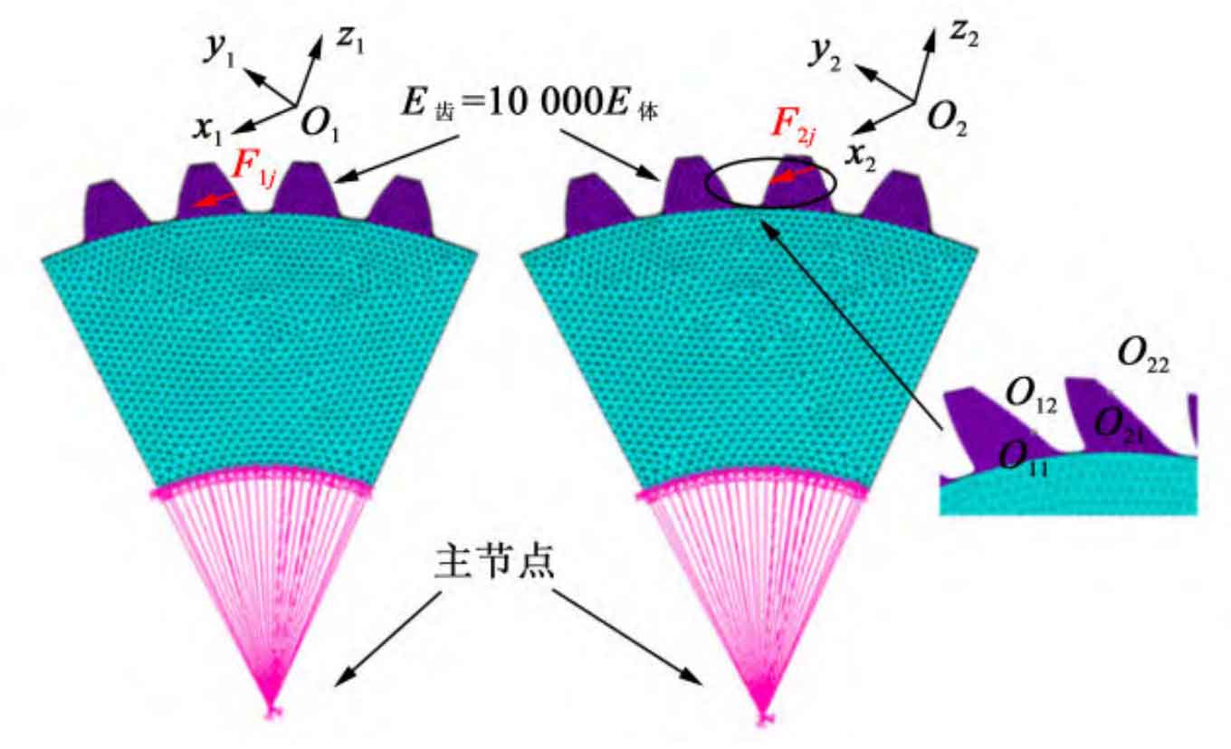
To calculate the displacement along the action line induced by the gear wheel body at the meshing point, the elastic modulus of the thin tooth of the straight bevel gear is set to 10000 times that of the wheel body. At this point, compared to the wheel body, the teeth can be regarded as a relatively rigid region, which can ignore the displacement caused by local Hertz contact and tooth elastic deformation. Establish a mass21 element at the midpoint of the tooth width of the thin film axis, couple it with the inner ring node, and apply full constraints. In Figure 2, O1-x1y1z1 and O2-x2y2z2 represent the local coordinate systems of the meshing points, respectively; Axes x1 and x2 respectively follow the direction of the action line. Apply force F1j along axis x1 at double tooth meshing position O1j, and force F2j along axis x2 at meshing position O2j (F1j=F2j=0) 5 N), and measure the displacement generated at Oij (i=1,2; j=1,2; the same below) along the direction of the action line. In order to make the calculation method in this article easier to understand, the definitions of each symbol are shown in Table 1. According to the finite element results, it can be concluded that:
| Symbol | Definition |
| Fij | The meshing force applied at Oij |
| kfi | Wheel stiffness when applying Fij force at Oij |
| Kfi | Wheel stiffness when applying F1j at O1j and F2j at O2j |
| δ1ij | When applying F1j at O1j, the displacement along the action line at Oij |
| δ2ij | When applying F2j at O2j, displacement along the action line at Oij |
| δij | When applying F1j at O1j and F2j at O2j, the displacement along the action line at Oij |
The load distribution coefficients Lsf1 and Lsf2 can be expressed as follows:

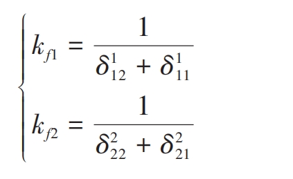
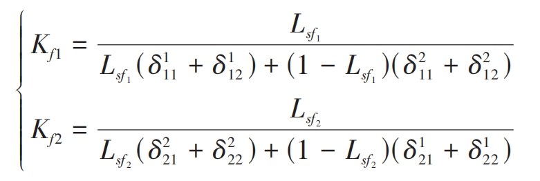
Based on the assumption of linear superposition, Kf1 and Kf2 can be expressed as follows:
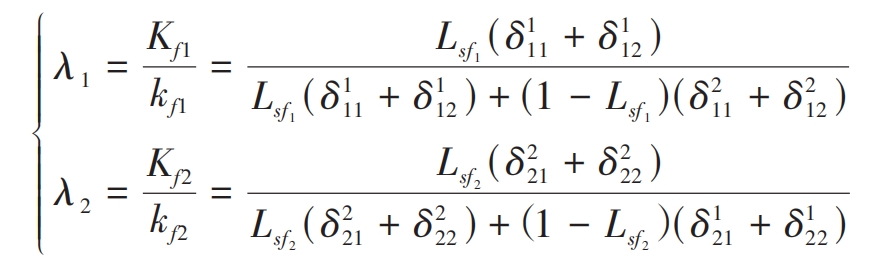
Equations (7) to (9) can be used to obtain the wheel body correction coefficient λ 1 λ 2 are:
Calculate the wheel body correction coefficients corresponding to each slice λ 1 λ 2. Substituting into equation (5) can obtain the double tooth meshing stiffness of straight bevel gear. Compared to the finite element model of straight bevel gear pairs, the thin plate finite element model is very simple and does not require setting contact pairs, normal penalty stiffness coefficients, solution methods, etc. Therefore, it can save most of the calculation time.
2. Calculation model for meshing stiffness of error tooth profile
2.1 Deviation of tooth profile of each thin plate caused by assembly error of straight bevel gear
There are many factors that affect the meshing stiffness of straight bevel gear. In addition to design and manufacturing errors, installation errors have a significant impact on the meshing stiffness of straight bevel gear. Therefore, in this article, only the deviation of tooth profile position caused by installation error (thin slice back cone error tooth profile) was considered, and its meshing stiffness model was established. According to national standards, installation errors can be divided into axis intersection angle error and axis intersection point error. Figure 3 shows the coordinate system relationship of assembly errors. In Figure 3, θ、ε They are axis intersection angle error and axis intersection point error, respectively; The coordinate systems S1 (O1-x1y1z1) and S2 (O2-x2y2z2) are fixedly connected to the main and driven gears, respectively, where z1 and z2 coincide with the axes of the main and driven gears; S1i (O1i x1iy1i
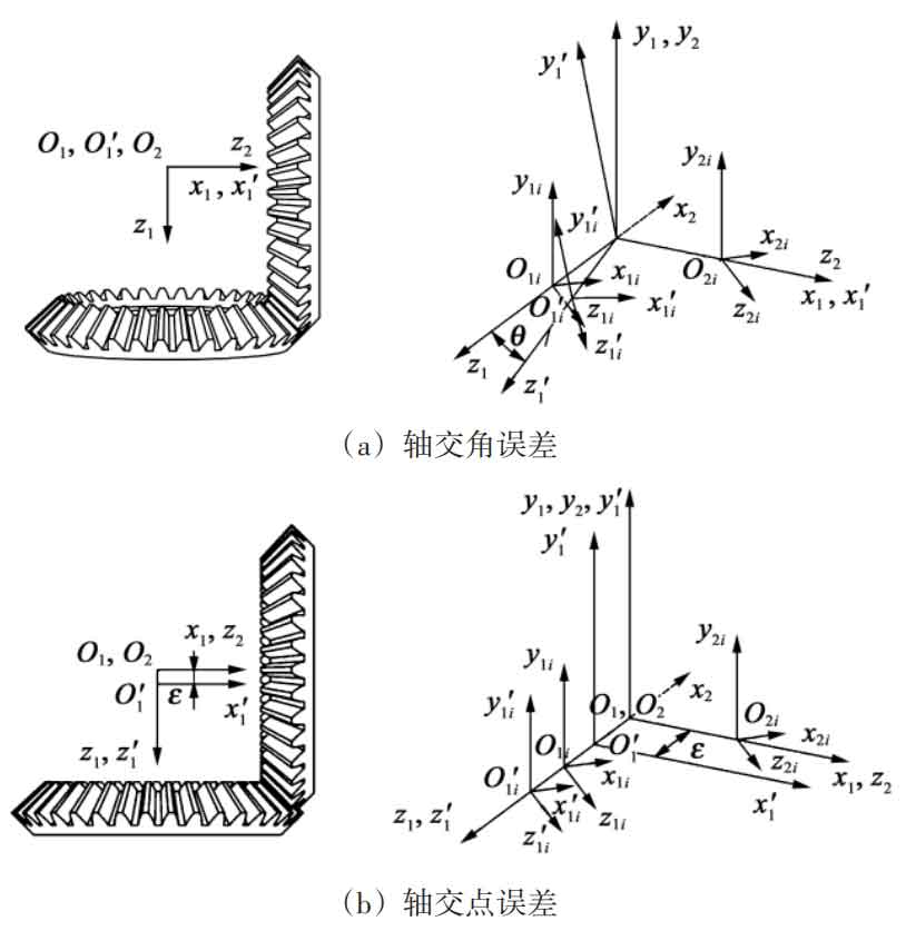
Z1i) and S2i (O2i-x2iy2iz2i) are the auxiliary coordinate systems at the i-th slice, where the angles between z1i, z2i, and z1 and z2 are respectively δ 1 δ 2.
As shown in Figure 3 (a), under the error of axis intersection angle, the coordinate system S1 rotates clockwise around axis x1 θ Transform the angle to position S ′ 1i as shown in the diagram. As shown in Figure 3 (b), under the error of the axis intersection point, the coordinate system S2 shifts along the axis z1 ε Change to position S ′ 1i in the diagram. Therefore, the tooth profile deviations Ei1 and Ei2 caused by the intersection angle and intersection point of the i-th slice are:
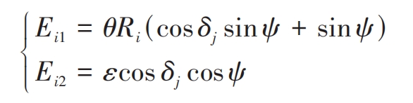
In the formula, δ J (j=1,2) is the main and driven wheel cone angle; Ri is the outer cone distance of the thin film i. When the driving gear rotates clockwise, ψ It can be expressed as:
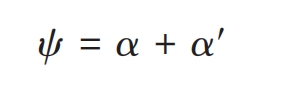
In the formula, α Is the pressure angle; α′ The angle between the center line of the main and driven gear teeth and the x1i direction of the driving gear sheet.
In addition, the angular deviation ei1 and ei2 caused by the intersection angle and intersection point of the i-th thin film are:
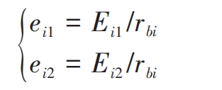
In the formula, rbi is the radius of the base circle corresponding to the thin film i.
2.2 Model of meshing stiffness for straight bevel gear with error tooth profiles
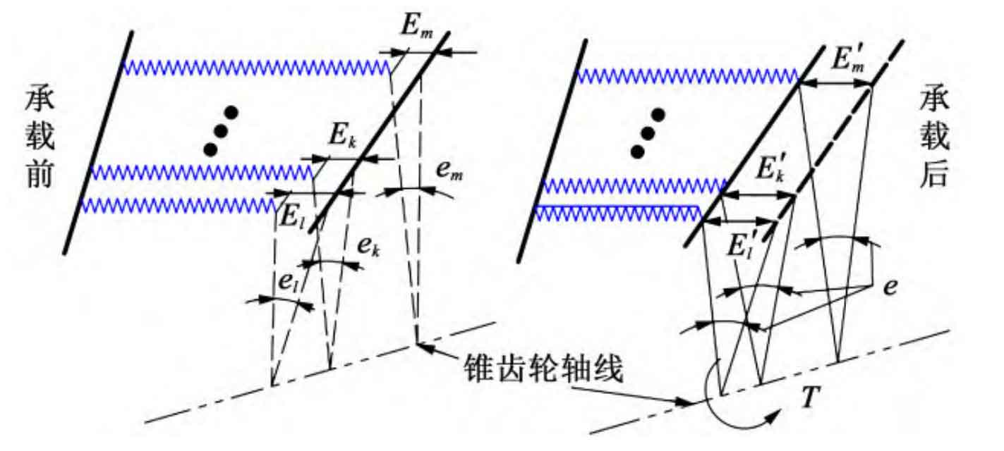
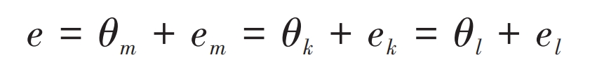
Under installation error conditions, the axis of the straight bevel gear will shift and skew, resulting in different meshing conditions for each thin tooth pair, often leading to edge contact and seriously affecting the transmission performance of the straight bevel gear. Therefore, the calculation of meshing stiffness under error conditions needs to determine whether each sheet is involved in meshing. Figure 4 shows the load-bearing contact process of thin plates of straight bevel gears under error conditions. In Figure 4, Ei (i=m, k, l, the same below) represents the tooth profile deviation of thin plate i; E ′ i is the sum of the deformation and tooth profile deviation generated by the thin plate under load; Ei is the angular deviation of the thin film; E is the sum of angular displacement and angular deviation generated by the loading of the thin film under error conditions; T is the applied external torque. Under the action of the load, as the driving wheel rotates, the angle deviation of the first contact sheet is definitely the smallest among all the sheets. Assuming that the angular deviation em of sheet m is the smallest among all sheets, that is, sheet m begins to make contact first. As the driving wheel continues to rotate, the thin film m begins to undergo elastic deformation, causing angular displacement at the center point θ m. When the sum of its angular deviation em is greater than the angular deviation ek of the thin film k, the thin film k begins to contact and deforms, bearing the load; If the load capacity cannot reach the load capacity of the straight bevel gear at this time, θ M will continue to increase until θ When the sum of m and em is greater than the angular deviation el of the tooth pair l, the tooth pair l begins to participate in meshing. And so on, until the load-bearing capacity of all the thin tooth pairs participating in meshing is equal to the external torque T of the straight bevel gear, the straight bevel gear is in a state of force balance and the deformation ends.
According to Figure 4, the angular displacement of straight bevel gear under load can be represented as:
According to equation (14), when the center point angular displacement of the thin plate tooth pair m is known, the center point angular displacement of the thin plate tooth pair i is:
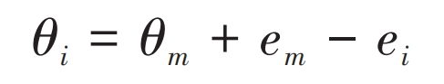
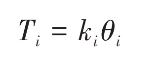
According to the principle of force balance, the load-bearing torque generated by straight bevel gear as a whole should be the sum of the load-bearing capacities of each pair of thin teeth in the meshing state, that is:
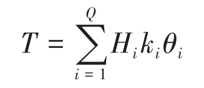
In the formula, T is the applied external torque; Q is the number of thin sheets involved in meshing under ideal conditions; Hi is the judgment factor, taken as 1 when the thin film participates in meshing, otherwise taken as 0; Ki is the torsional meshing stiffness of thin plate i; θ I is the angular displacement of the center point of the thin film i.
Enter i θ M0, by judging θ Is i greater than 0 to obtain the thin sheets involved in meshing. If the relative error between the load-bearing capacity and the external torque T of the thin tooth pairs participating in meshing is greater than an acceptable value ξ, increase θ Step size of m, continue to cycle through the calculation; Otherwise, output θ M θ i. The loop ends. This article sets the initial value of i to 1, θ M0=0, Δ= 10-5 rad, ξ= 0.01%.
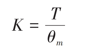
When considering straight bevel gear pair as a whole, under the action of external load, the angular displacement of the center point of the straight bevel gear is the same as the center angular displacement of the first contact thin tooth pair, that is, the center angular displacement of the thin tooth pair m. Therefore, the comprehensive torsional meshing stiffness of straight bevel gear pairs under error conditions can be expressed as:
In addition, based on the shape variables of each slice δ i. The load borne by each thin film can be obtained as:
3. Example analysis
Taking a pair of straight bevel gear as an example (parameters shown in Table 2 for finite element analysis, the finite element calculation results are compared with the method proposed in this paper and traditional analytical methods to verify the accuracy of the proposed method.
| Parameter | Numerical value | Parameter | Numerical value |
| Module/mm | 1.75 | Tooth top height coefficient h*a | 1 |
| Number of teeth in the driving gear z1 | 35 | Tooth clearance coefficient c* | 0.25 |
| Number of driven gear teeth z2 | 35 | Hole radius rk/mm | 15 |
| Tooth width b/mm | 10 | Poisson’s ratio ν | 0.3 |
| Pressure angle α/ (°) | 20 | Elastic modulus/GPa | 206 |
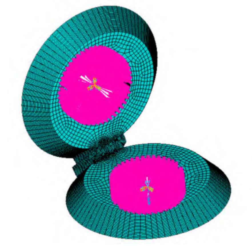
3.1 Finite element model of straight bevel gear
Figure 5 shows the finite element model of straight bevel gear. Establish mass21 elements at the midpoint of the tooth width of the main and driven gear axes, and couple them with the inner surface nodes of the straight bevel gear; Reserve the axial rotational freedom of the driving gear and apply a torque of T=100 N · m; Apply full degree of freedom constraints to the driven gear. The normal penalty stiffness coefficient is set to 1, and the penetration coefficient is set to 0 1. Use the augmented Lagrangian method for solving.
In this model, by calculating 10 meshing positions within one meshing cycle, the torsional meshing stiffness of the straight bevel gear can be obtained, which is:
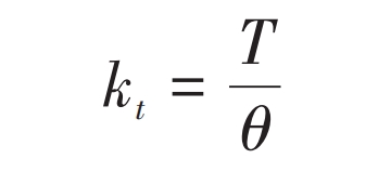
In the formula, T is the torque applied to the driving wheel; θ The angular displacement of the coupling center point for the driving wheel.
3.2 Verification of meshing stiffness of straight bevel gear
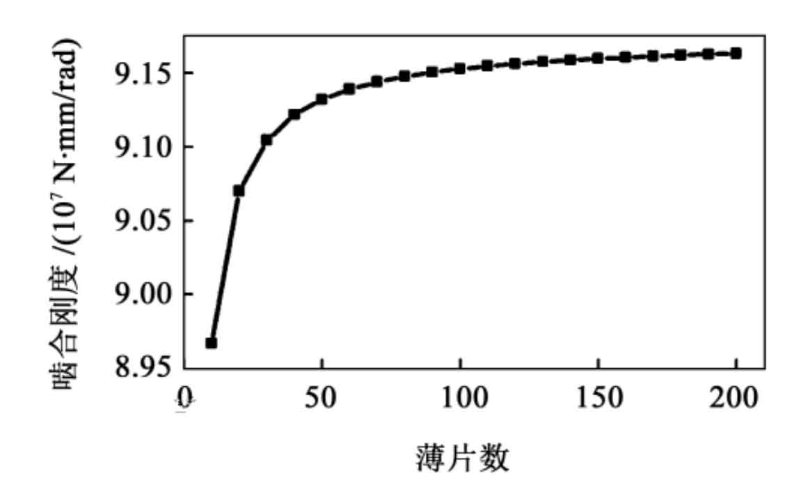
During the meshing period, grid independence verification is carried out based on the meshing stiffness of the straight bevel gear when it first enters double tooth meshing, with a rolling angle of 0 °, as shown in Figure 6. From Figure 6, it can be seen that the convergence of this method is good. When the number of slices is greater than 60, the meshing stiffness value tends to stabilize.
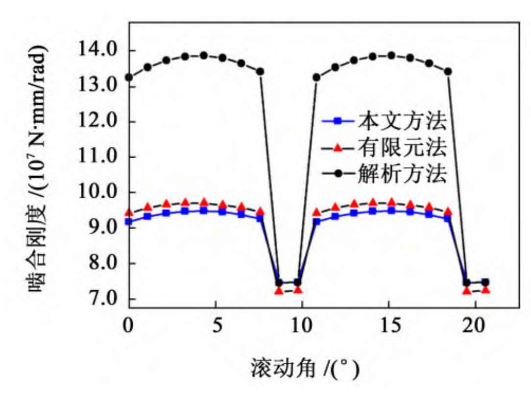
When the number of thin plates is 60, the comparison of the calculation results of the meshing stiffness of straight bevel gears using the method proposed in this paper, traditional analytical method, and finite element method is shown in Figure 7. As shown in Figure 7, the stiffness error of the double tooth meshing of the straight bevel gear obtained by the analytical method is relatively large, about 40%; The single double tooth meshing area of the straight bevel gear calculated by the method in this article is basically consistent with the finite element method, and the calculated results are also relatively close. The error of the double tooth meshing stiffness is about 2%, and the error of the single tooth meshing stiffness is about 3%. This indicates that the method proposed in this article can accurately calculate the meshing stiffness of straight bevel gear pairs.
As shown in Table 3. From the comparison of the calculation time of the method, analytical method, and finite element method in Table 3, it can be seen that in cases where the calculation accuracy is close, the calculation time of the method in this paper (including the time for calculating the wheel stiffness correction coefficient) is much smaller than that of the finite element method, which is about 0 3%; In addition, the accuracy of the double tooth meshing stiffness calculated by the method in this article is much higher than that of the analytical method, with an improvement of about 95%. In summary, it indicates that the method proposed in this article can quickly and accurately calculate the meshing stiffness of straight bevel gears.
| Computing method | Relative error of single tooth meshing stiffness/% | Relative error of double tooth meshing stiffness/% | Calculation time/min |
| Article Method | 3 | 2 | 5 |
| Analytic method | 3 | 40 | 0.4 |
| Finite element method | — | — | 1 440 |
3.3 Analysis of meshing stiffness and load distribution considering assembly errors
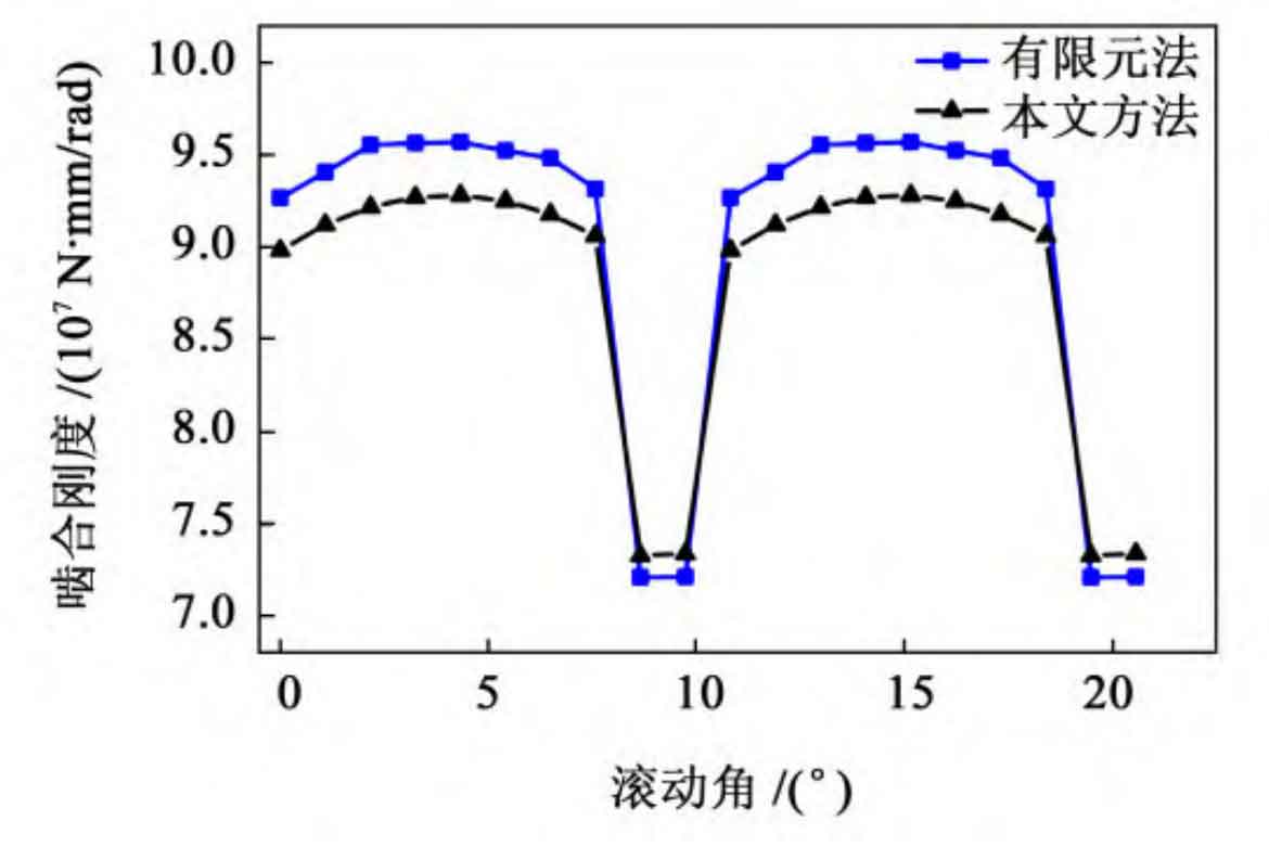
To verify the accuracy of the calculation method in this article under assembly error conditions, the axis intersection point error is taken ε The mesh stiffness calculation results of this paper’s method and finite element method for straight bevel gear are shown in Figure 8, which is 80 µ m. From Figure 8, it can be seen that the calculation error of double tooth meshing stiffness is about 3%, and the calculation error of single tooth meshing stiffness is about 2%, indicating that this method also has accuracy in calculating meshing stiffness when considering assembly errors.
According to the requirements of the national standard GB/T 11365-2019 for the installation accuracy of straight bevel gears, the shaft intersection angle error is taken separately θ 0 °, 0 01 °, 0 015 ° and 0 02 °, axis intersection error ε At 0, 30, 60, and 90 µ m, the corresponding meshing stiffness calculation results of the straight bevel gear pair are shown in Figure 9 and Figure 10, respectively. From Figures 9 and 10, it can be seen that as the intersection angle error and intersection point error of the straight bevel gear increase, the meshing stiffness of the straight bevel gear decreases. As the mesh stiffness of straight bevel gear decreases, it will lead to mesh deformation and increased transmission errors, thereby affecting the transmission performance and service life of straight bevel gear.
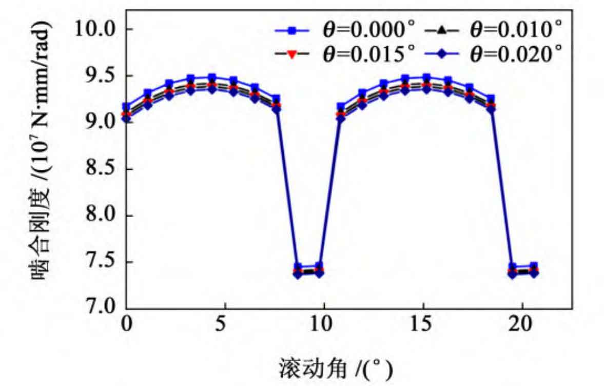
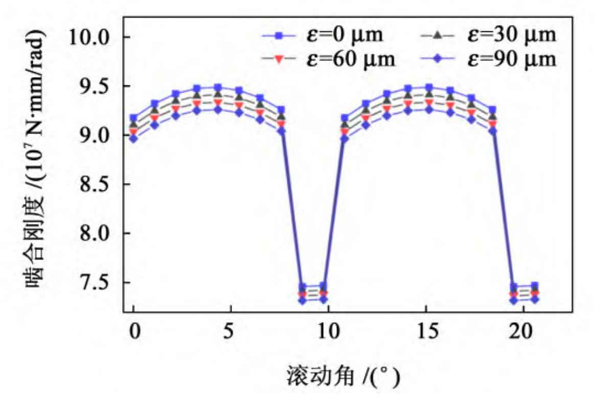
Figure 11 shows the distribution of center point angular displacement and tooth surface load of straight bevel gears under ideal conditions. From Figure 11 (a), it can be seen that under error free conditions, the angular displacement of the center points of each thin plate of the straight bevel gear increases first and then decreases from the tooth root to the tooth top. This is because only one pair of teeth bears the load in single tooth meshing, while two pairs of teeth bear the load in double tooth meshing, resulting in a large corresponding angular displacement in single tooth meshing; From Figure 11 (b), it can be seen that the maximum load bearing position is at the large end of the straight bevel gear during single tooth meshing. This is because the stiffness of the thin plate meshing at the large end is greater than that at the small end, resulting in a higher torque bearing at the large end.
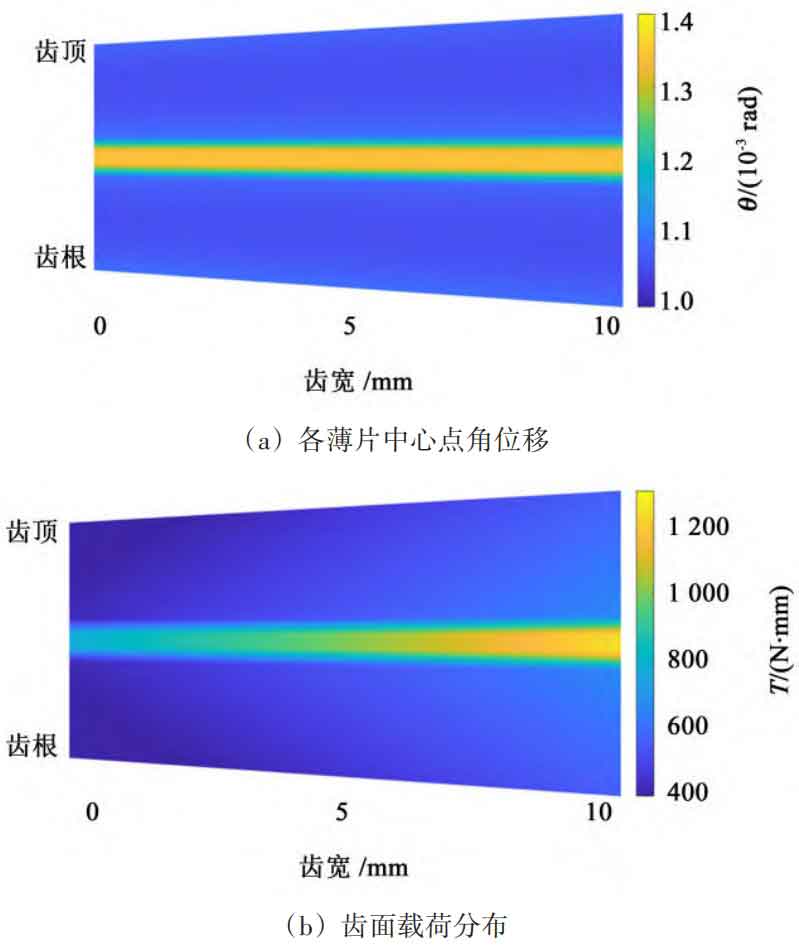
Figure 12 shows the axis intersection angle error θ= Distribution diagram of angular displacement and tooth surface load at the center point of each thin plate of straight bevel gear at 0.01 °. According to Figure 12 (a), it can be seen that the angular displacement generated by the load on the center point of the small end thin plate of straight bevel gear is the largest. This is because the small end angular deviation is the smallest under the state of axial intersection angle error, and it participates in meshing first during the meshing process, resulting in the angular displacement of the center point being the largest among all participating thin plates in meshing; As shown in Figure 12 (b), the maximum load that a straight bevel gear can withstand is at the small end of a single tooth mesh.
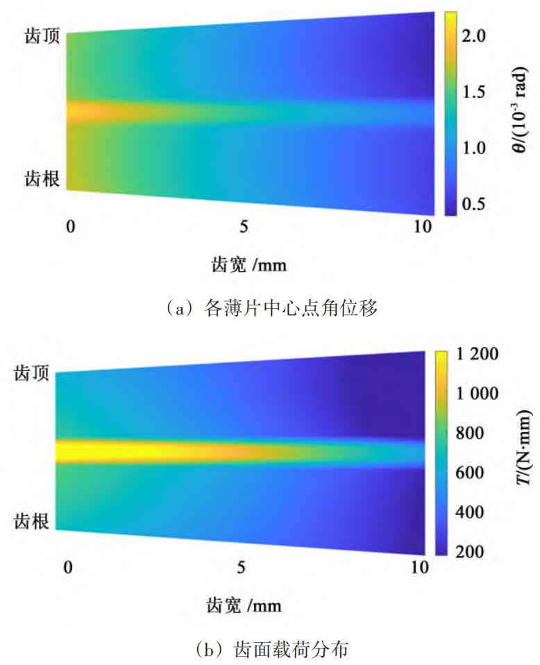
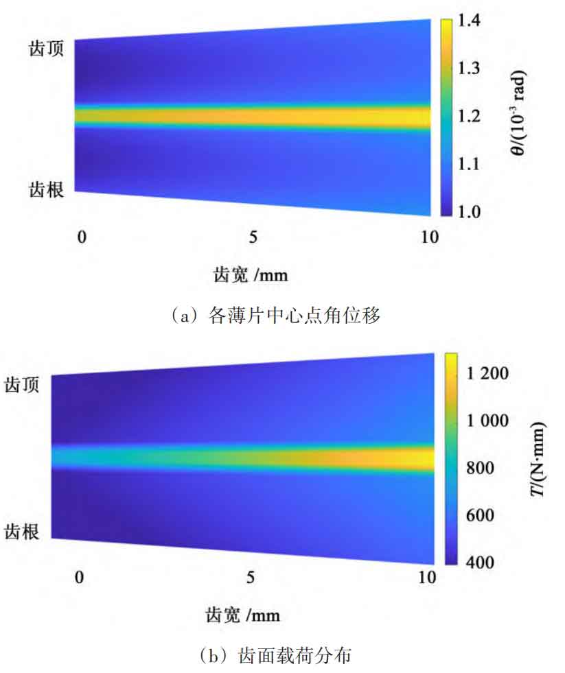
Figure 13 shows the error of axis intersection points ε= Distribution diagram of angular displacement and tooth surface load at the center point of each thin slice of straight bevel gear at 90 µ m. According to Figure 13 (a), it can be seen that the angular displacement generated by the load on the center point of the large end thin plate of the straight bevel gear is the largest. This is because the deviation of the large end angle is the smallest under the state of axis intersection error, and it participates in meshing first during the meshing process, resulting in the angular displacement of the center point being the largest among all participating thin plates. From Figure 13 (b), it can be seen that the maximum load borne by the straight bevel gear is at the large end during single tooth meshing.
In summary, assembly errors in straight bevel gear result in severe off load during the transmission process, leading to meshing deformation and increased transmission errors. This will reduce the load-bearing capacity of the straight bevel gear pair and seriously affect its service life. Therefore, in practical engineering, the installation accuracy of straight bevel gear pairs should be improved as much as possible to ensure their service life.
4. Conclusion
This article focuses on the efficient calculation of time-varying mesh stiffness of straight bevel gear and conducts the following research:
1) Based on the principle of back cone equivalence, the straight bevel gear is equivalent to a series of straight cylindrical gears, and the meshing stiffness of each thin plate is calculated using the energy method. In the calculation of double tooth meshing stiffness, the coupling effect between tooth pairs during multi tooth meshing is considered, and the finite element method is used to introduce a wheel stiffness correction coefficient to reduce the calculation error of double tooth meshing stiffness.
2) Comparing the method, analytical method, and finite element calculation results presented in this paper, the results show that the error in calculating single tooth meshing stiffness is about 3%, and the error in calculating double tooth meshing stiffness is about 2%. Moreover, the calculation time is much shorter than the finite element calculation time, which verifies the accuracy and efficiency of the method proposed in this paper.
3) By solving the angular displacement at the center point of each thin tooth pair of the straight bevel gear under load, the meshing stiffness, angular displacement at the center point of each thin tooth, and tooth surface load distribution of the straight bevel gear under error state were calculated; Compared with the finite element method, the accuracy of meshing stiffness calculation under error conditions was verified. This article combines the advantages of finite element method and analytical method, which significantly improves the efficiency of calculating the time-varying mesh stiffness of straight bevel gears while also possessing high calculation accuracy; In addition, it has also been verified that the method proposed in this paper still has accuracy under installation error conditions. However, it is worth noting that, in addition to installation errors, the time-varying mesh stiffness of straight bevel gear is also affected by tooth profile errors caused by surface roughness, as well as friction and lubrication during tooth surface meshing. However, the method proposed in this article cannot be considered and further improvement is needed.