The ratio of the relative tangential speed of the gear pair between the tooth surfaces at the meshing point and the tangential speed of the shop is the slip rate.

Sliding rate (relative sliding rate) is defined as:
In the equation, 1 and 2 are dominant, and the sliding rate of driven wheel (relative sliding rate);
The tangential velocity component, m/s, at the meshing point of driven wheels with Vt1 and Vt2 as main parts.
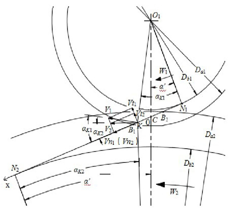
Fig. 1 is a sketch of the transmission speed and its components at any engagement point K of the gear drive. There are:

In the formula, Vn1 and Vn2 are dominant, and the normal speed component of driven wheel is dominant; V1 and V2 are dominant, and the absolute speed of driven wheel is dominant; Alphak1 and Alphak2 are dominant, and the pressure angle at the engagement point of driven wheel is also dominant.
As the position of the engagement point changes, so does the transmission speed at the engagement point. It can be seen that the slip rate is actually a function of the coordinates of the engagement point position.In order to get this driving variation law more clearly, the meshing line coordinate system is now established with gear meshing joint C as coordinate origin O and CB1 direction as coordinate x-axis orientation, as shown in Figure 1.

It can be derived from Formula (1) and Formula (3)

If the coordinate at any engagement point K is x and the formula for calculating the sliding rate in formula (4) is converted into the coordinate position representation, then there are:

Where m is gear module, Z1 and Z2 are main driven wheels, U is gear ratio, and alpha’is pressure angle of gear engagement point.
