
Figure 1-2 shows the maximum equivalent stress nephogram of the main and driven helical gears, and figure 3-13 shows the equivalent stress nephogram of the helical gear pair during meshing. Because there are many frames of dynamic contact simulation animation, they are not listed here one by one. In order to facilitate the comparison of stress results, the maximum equivalent stress in each frame of animation is the ordinate and the meshing time is the abscissa, which are programmed in MATLAB. Fig. 14 and FIG. 15 respectively list the maximum equivalent stress change curve of the driving and driven helical gears in the whole process from meshing to disengagement.
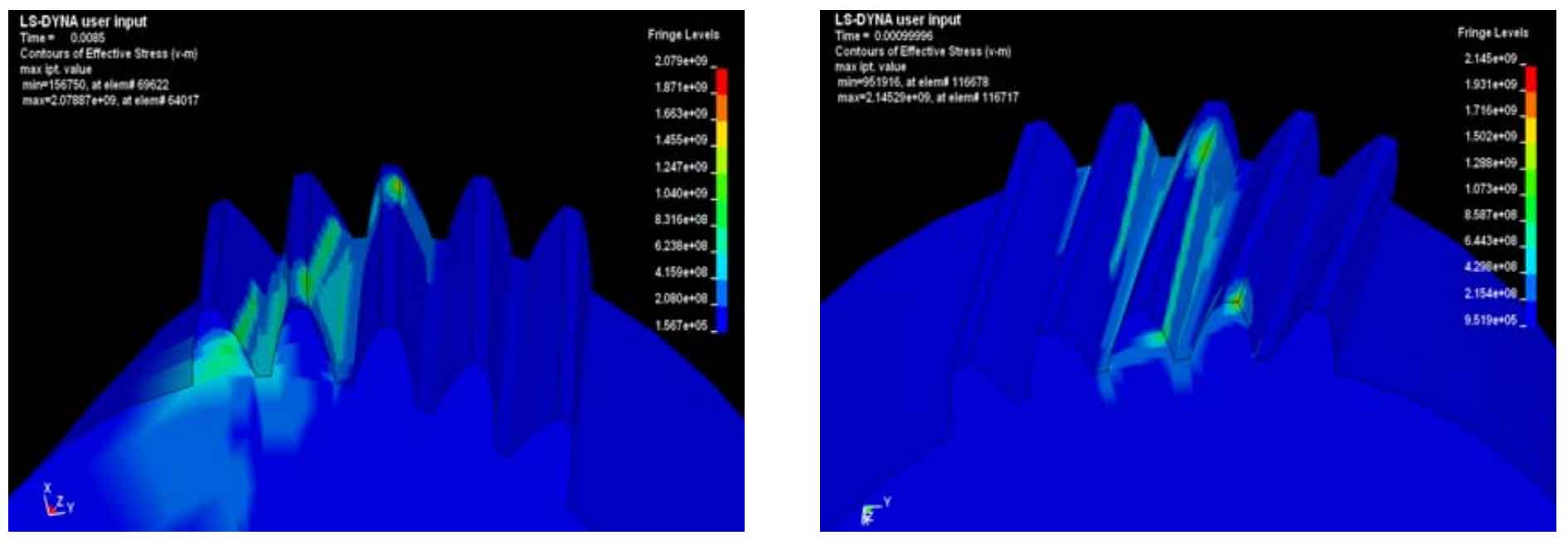
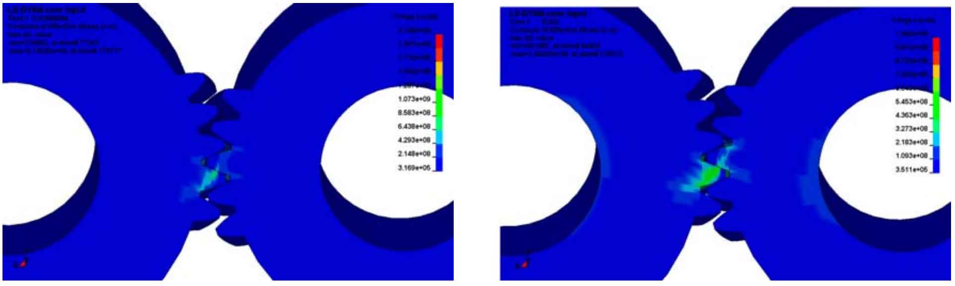
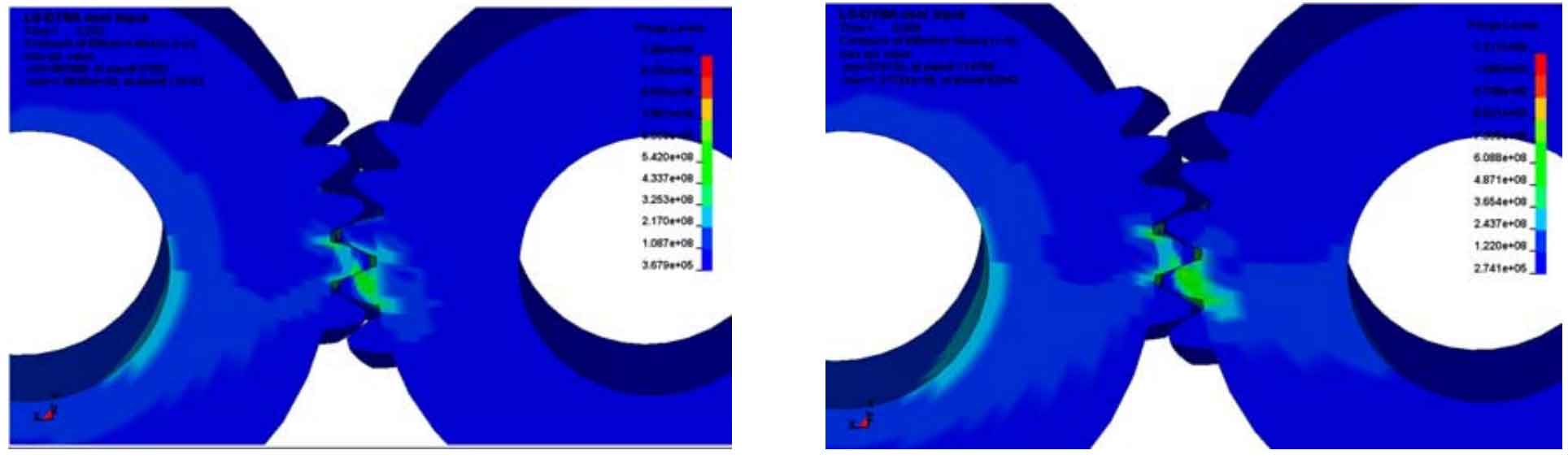
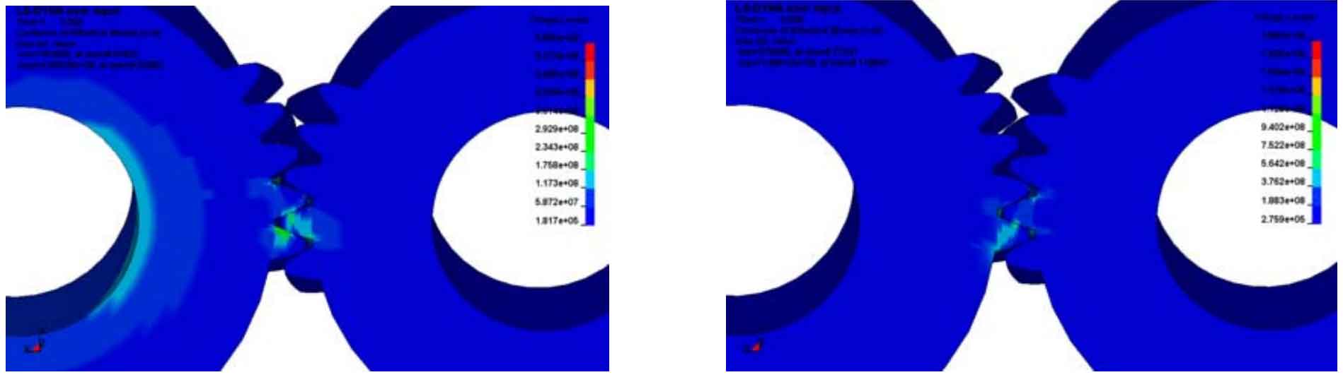
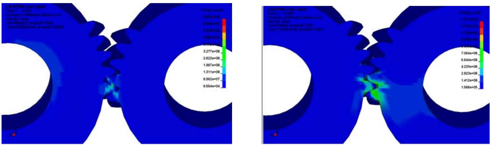
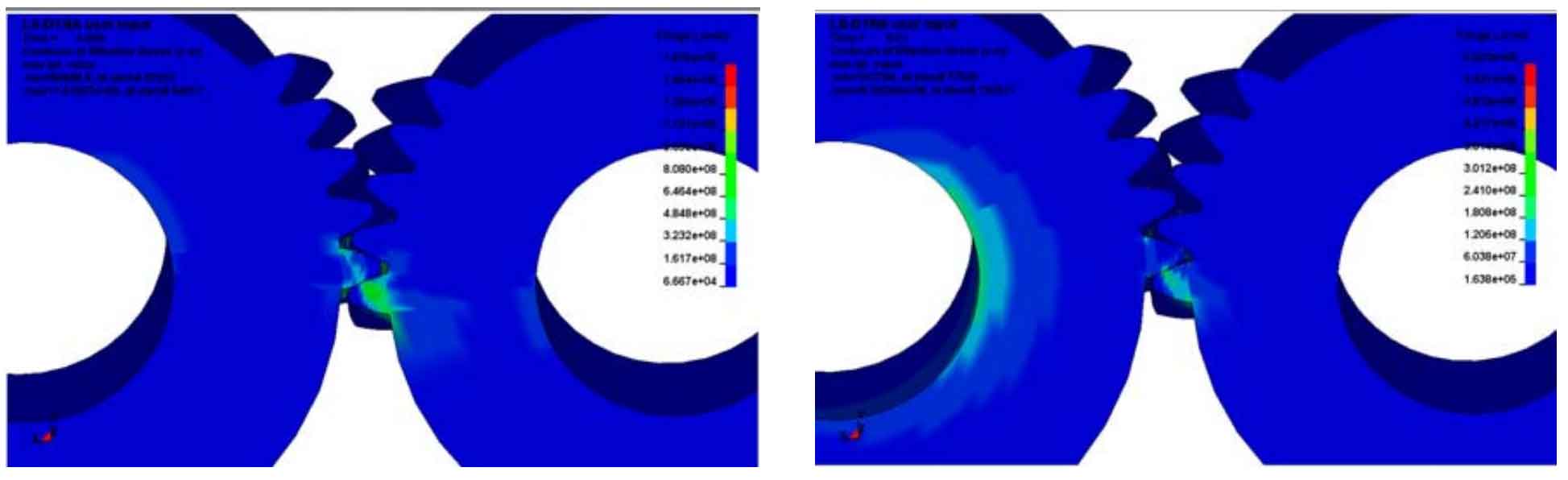
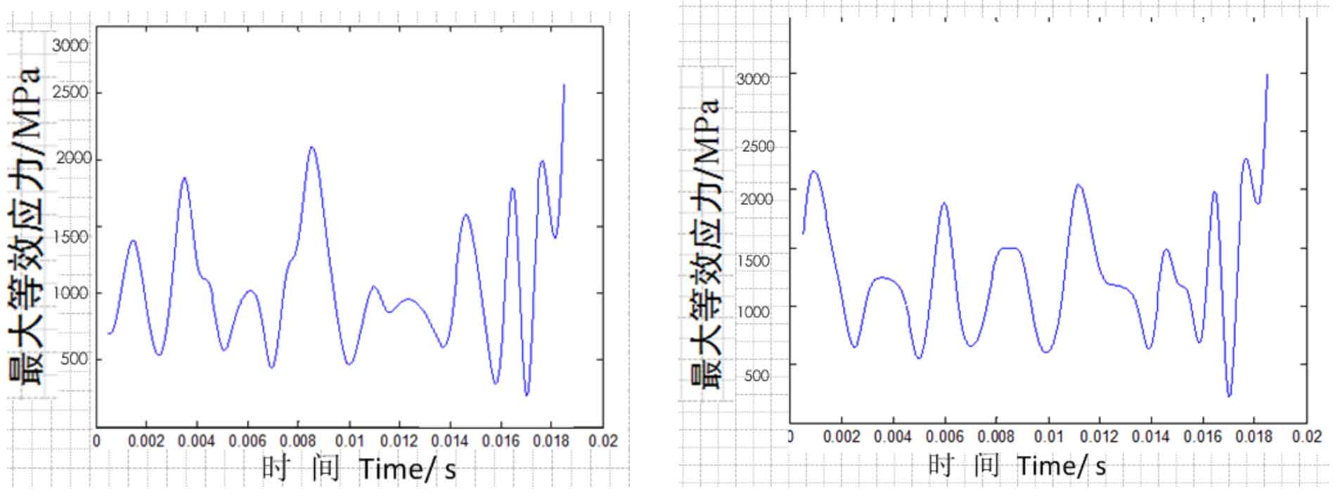
From the stress nephogram 1-2, it can be seen that the tooth surfaces of the two helical gears are in contact, and the contact lines of the two helical gears are inclined lines with a certain angle to the edge of the teeth, which is consistent with the actual working conditions. It can also be seen intuitively from figure 2-3 that during the movement of the gear, due to the symmetry of the helical gear, the change of the maximum equivalent stress of the helical gear after stable operation shows a certain regularity. The maximum equivalent stress of the driving helical gear is 2079mpa at 0.0085s, and the maximum equivalent stress of the driven helical gear is 2145mpa at 0.001s, which does not meet the strength requirements, The position where the stress is too large is the meshing position of the helical gear.