
The application of load is a very important step in the contact analysis of helical gears. The magnitude and direction of the applied load directly affect the results of static contact analysis. Since solid45 element has only x, y and Z displacement degrees of freedom and no rotation degrees of freedom, the torque cannot be directly applied to the model. Therefore, the loading mode and boundary conditions should be changed accordingly. In order to achieve the rotation effect, this paper converts the torque into the tangential force acting on the inner ring node of the helical gear, so that the synthetic result of the tangential force is equivalent to the torque rotating around the helical gear axis.
First, you need to convert the default total coordinate system to cylindrical coordinate system. At this time, the X and Y directions change to R and Y accordingly θ , Then convert all nodes to cylindrical coordinate system. It is assumed that the driven wheel does not move at the moment when the driving wheel engages with the driven wheel, so all nodes on the inner ring surface of the driven wheel shaft rod are constrained, and all degrees of freedom of the nodes on the surface of the driving helical gear shaft rod except rotation are constrained, so that the driving helical gear can not move but rotate.
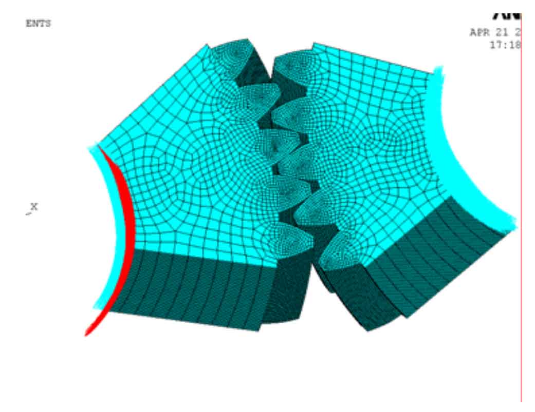
Finally, constraints and tangential forces are applied to all nodes on the inner ring surface of the driving helical gear shaft. The specific load and boundary conditions are added as shown in the figure.