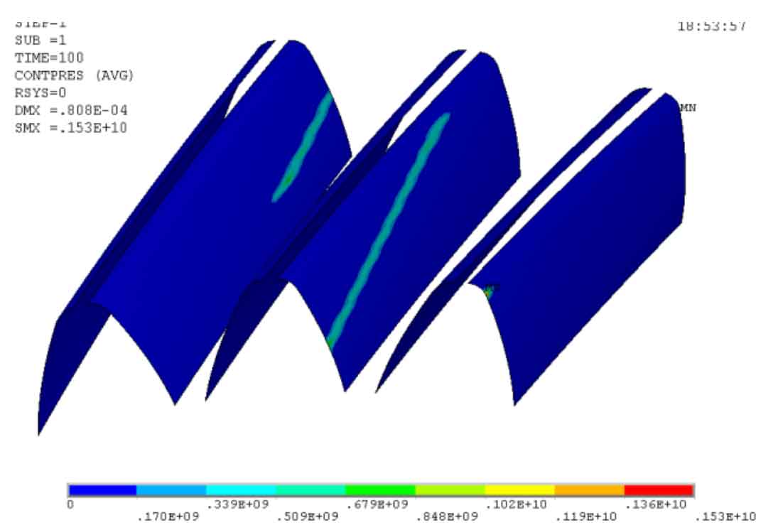
Through the general post processor, we can view and analyze the solution results, observe various displacement, stress and other cloud diagrams, clearly and intuitively see the distribution of displacement and stress of helical gear model, and obtain the displacement, stress and other data of nodes in all directions. Fig. 1 is the cloud diagram of equivalent effect stress on the contact surface, the maximum contact stress is 1530mpa, the maximum contact stress of helical gear pair calculated traditionally based on Hertz theory is 1215.9mpa, the helical gear material is 20crmoti, and the allowable contact stress after heat treatment is 1600mpa.

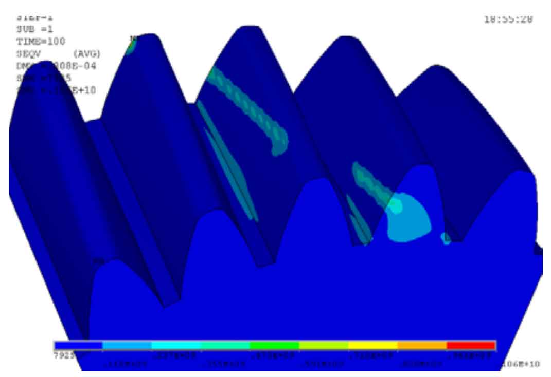
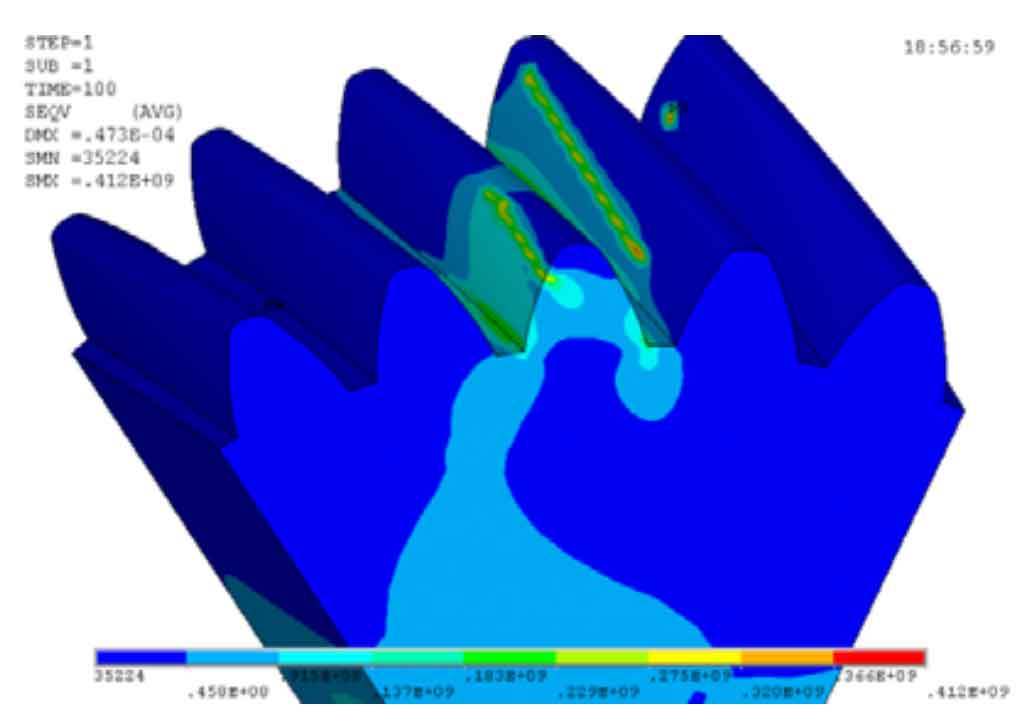
The contact stress obtained by the traditional calculation formula is smaller than that calculated by the finite element method, which shows that it is safe to design and check according to the finite element method in engineering. It can be seen from Fig. 1-3 that the equivalent stress of the main gear and the driven gear in different meshing directions is the maximum stress in Fig. 3-3. The tooth surfaces of the two helical gears are in contact, and the contact lines of the two helical gears are inclined lines with a certain angle with the edge of the teeth, which is consistent with the actual working conditions; The equivalent stress near the contact line is much larger than that far away from the contact line, and the tooth root stress is much smaller than the contact stress in the meshing process. The maximum equivalent stress appears at the edge of the contact line between the two teeth. The maximum equivalent stress of the driving and driven helical gears are 1060mpa and 412mpa respectively. Therefore, the static contact strength of the driving and driven helical gears meets the requirements.

The contact stress of the driven helical gear is greater than that of the driving helical gear. The reason is that all degrees of freedom of the driven helical gear are constrained in the static simulation process of the helical gear, and the torque is applied to the driving helical gear. At the moment of the static contact of the helical gear, the impact of the driven helical gear is greater than that of the driving helical gear. The place where the maximum contact stress occurs in the driving and driven helical gears is where the teeth have just entered the meshing, and the meshing stress is relatively large. At the same time, the sharp angle of the teeth is easy to cause stress concentration in the meshing process. One of the measures to avoid stress concentration at the sharp angle is to modify the helical gear.

