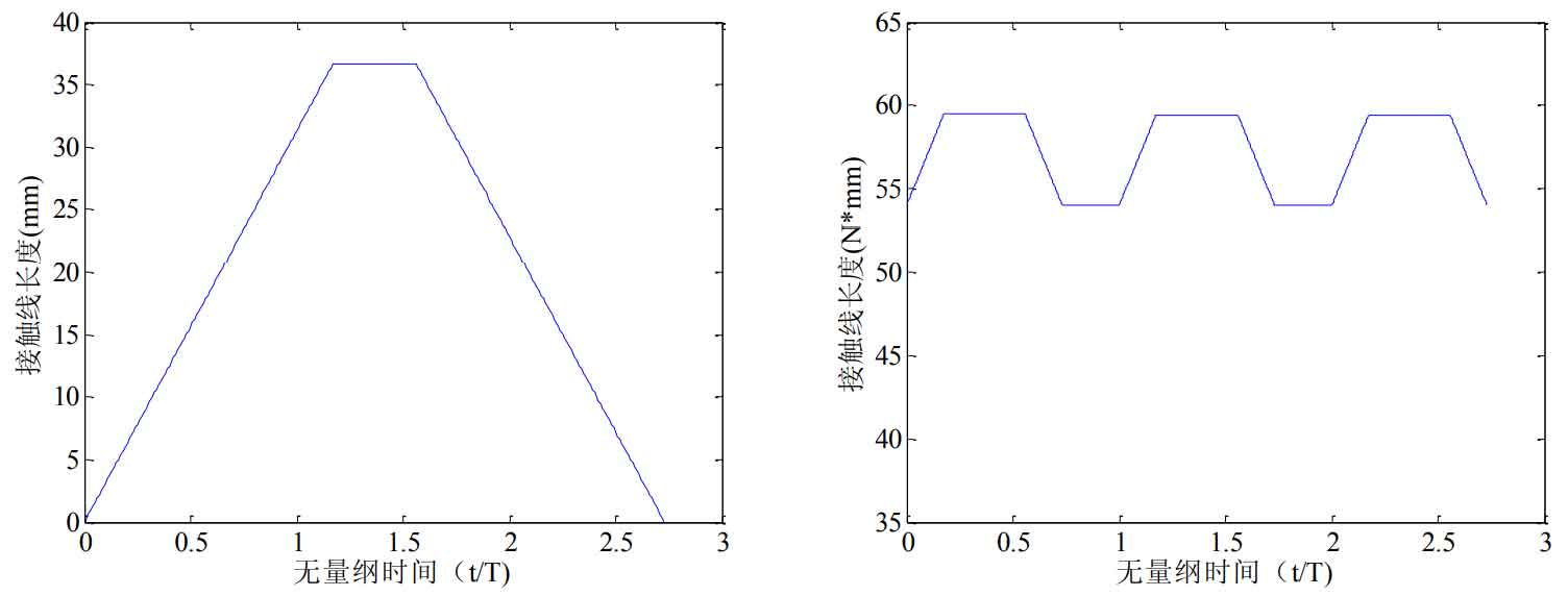
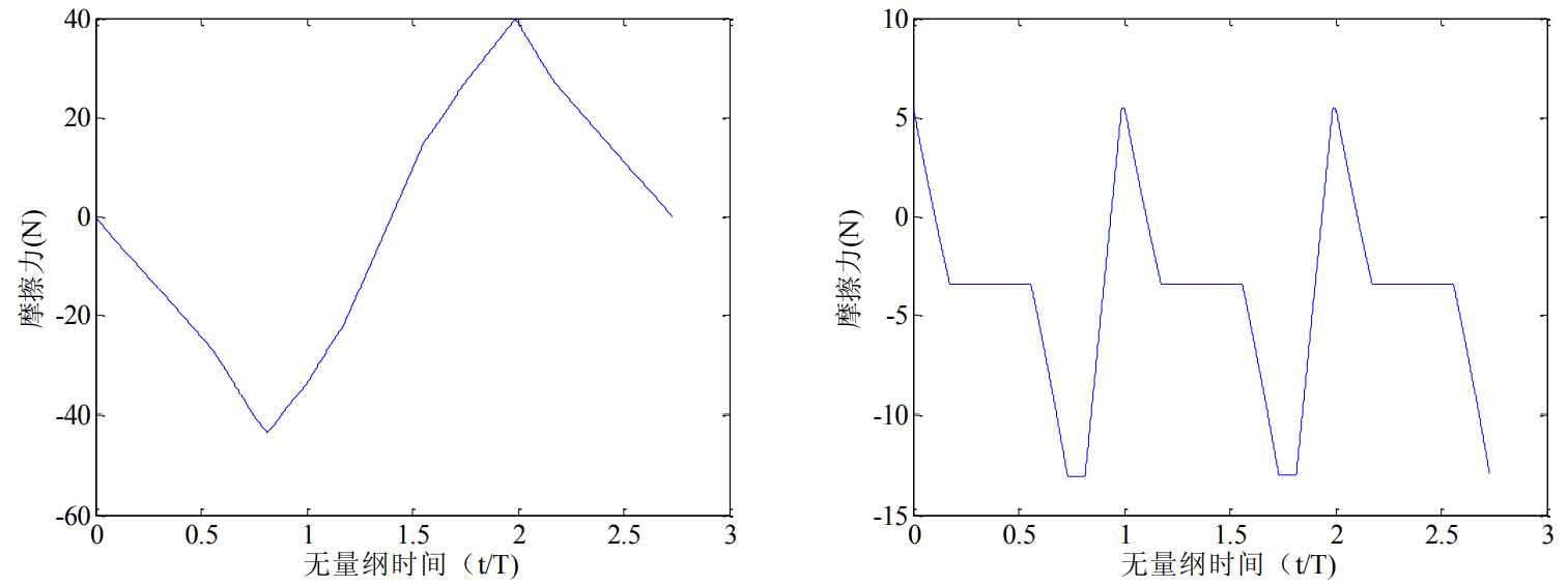
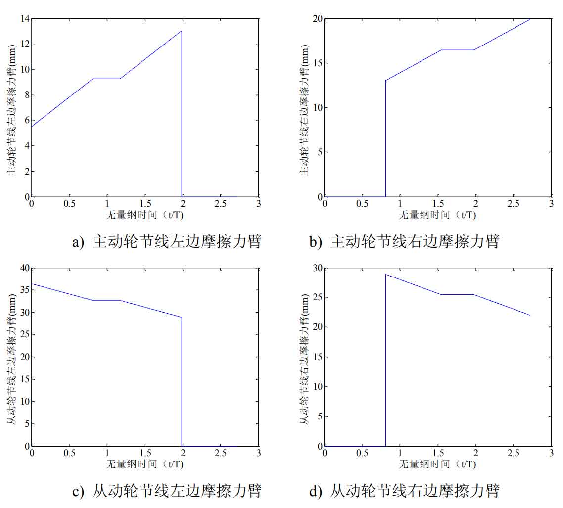
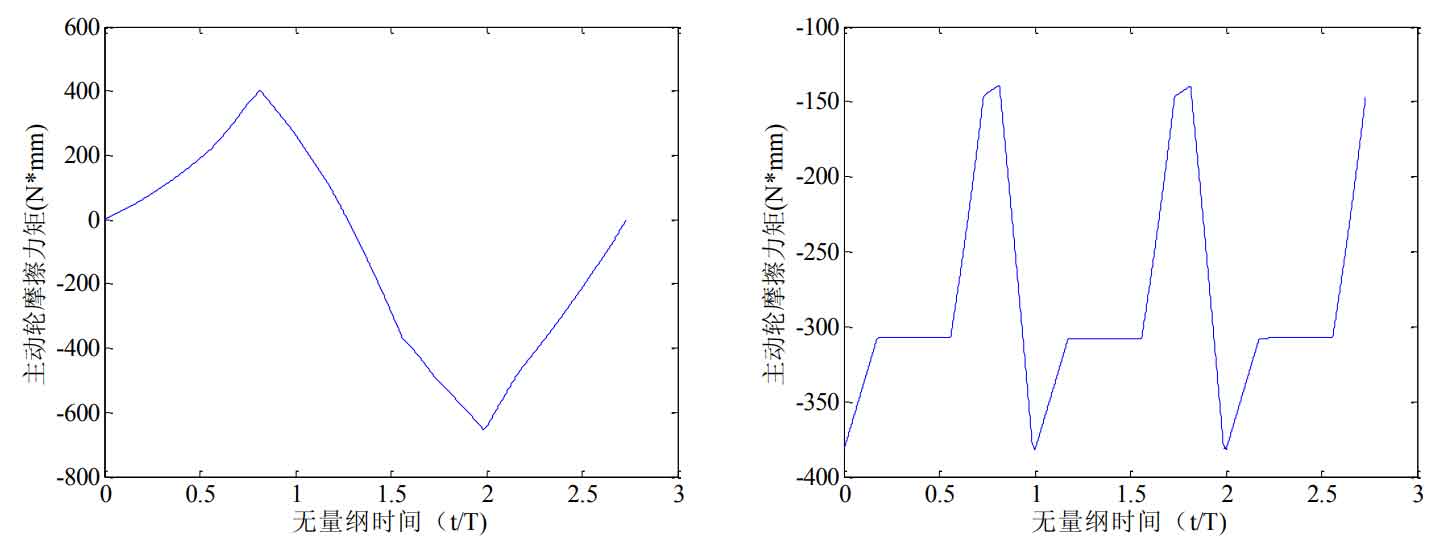
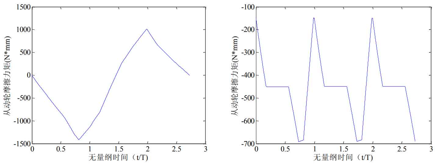
The calculation program of friction force and friction torque is compiled by MATLAB software. The total comprehensive contact line length of the total meshing tooth pairs in one meshing cycle of the helical gear system is obtained by superposition of the contact line length of a single pair of helical gears, as shown in Fig. 1. The friction force of a single pair of teeth calculated according to the length of the contact line on the left and right sides of the pitch line of a single pair of teeth and the normal meshing force per unit contact line length, As shown in Fig. 2 (a), the total meshing tooth pair friction in one meshing cycle of helical gear system is shown in Fig. 2 (b) As shown in Figure 3, due to the interaction between the friction force of the pair of teeth entering and exiting the meshing contact of the helical gear system, the friction force remains constant for a period of time. The friction force arms on the left and right sides of the pitch line on the single pair of teeth contact line of the driving wheel and the driven wheel are shown in Figure 3. The single pair of teeth of the driving wheel and the driven wheel are calculated from the friction force on the single pair of teeth and the friction force arm on the single pair of teeth contact line The friction torque, as shown in Fig. 4 (a) and Fig. 5 (a), corresponds to the total friction torque of the total meshing tooth pair in one meshing cycle of the helical gear system, as shown in Fig. 4 (b) and Fig. 5 (b).
① Influence of different friction coefficients on friction excitation
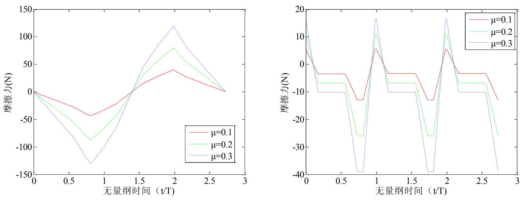
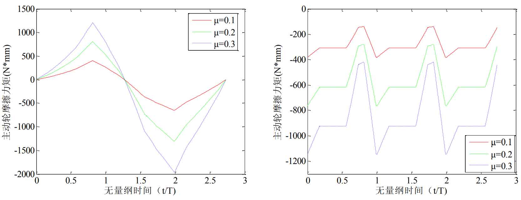
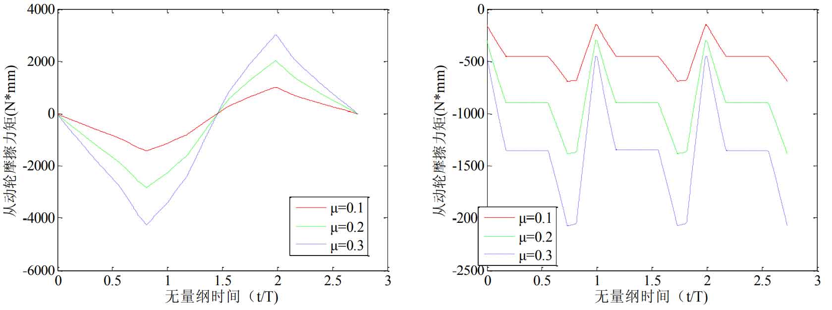
The effects of different friction coefficients on the friction of single pair of teeth and total meshing teeth are shown in Figure 6. Fig. 6 shows that with the increase of friction coefficient, the amplitude of single tooth pair friction and total meshing tooth pair friction increases. Fig. 7 and Fig. 8 show the effects of different friction coefficients on the single pair tooth friction of driving wheel and driven wheel and the total meshing teeth on the friction torque, and its amplitude also increases with the increase of friction coefficient.
② Influence of different helix angles on friction excitation
Calculate different helix angles Influence of (18 °, 19 °, 20 °) on friction excitation of helical gear system. The length of contact line of single pair of helical gear teeth and total meshing teeth in one meshing cycle changes, as shown in Fig. 9. The friction of single pair of teeth and total meshing teeth with different helix angles are shown in FIG. 10. With the increase of helix angle, the overall amplitude of friction of single pair of teeth decreases; the overall amplitude of friction of total meshing teeth decreases with the increase of helix angle It increases with the increase of helix angle, and the holding time decreases with the increase of helix angle. Fig. 11 and FIG. 12 show the effects of different helix angles on the friction force of single pair of teeth of driving wheel and driven wheel and the friction torque of total meshing teeth. With the increase of helix angle, the overall amplitude of friction torque of single pair of teeth decreases; The overall amplitude of the friction torque of the total meshing tooth pair increases with the increase of the helix angle, and the time to maintain the constant value decreases with the increase of the helix angle.
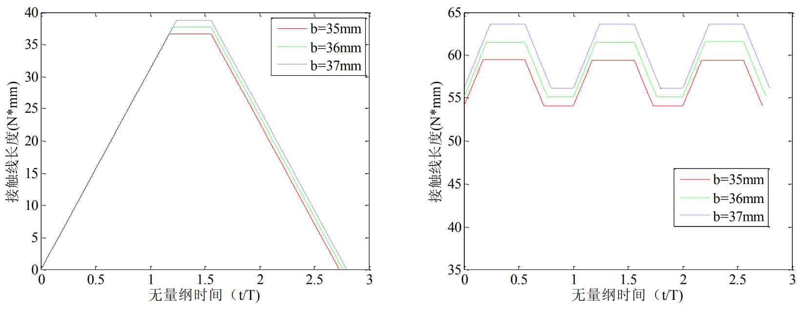
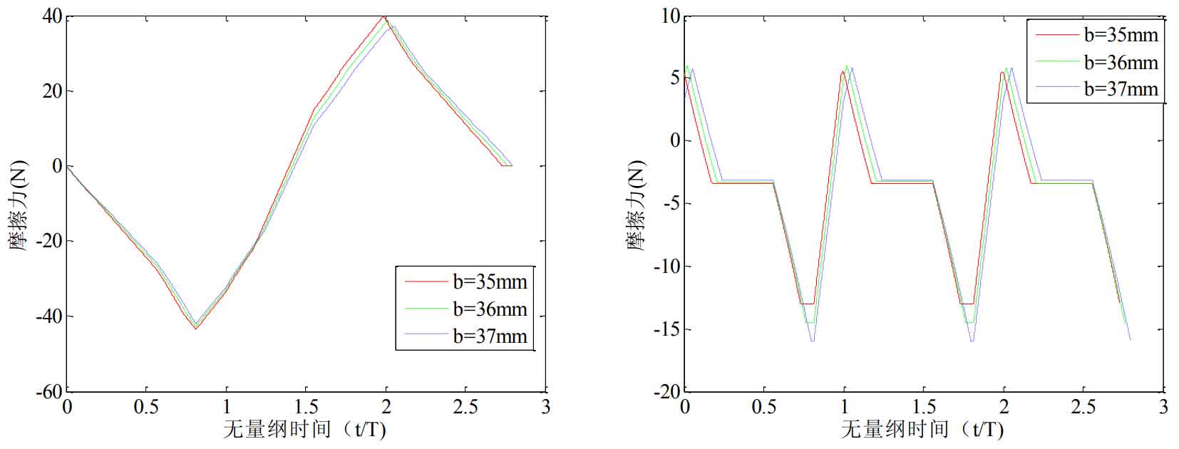
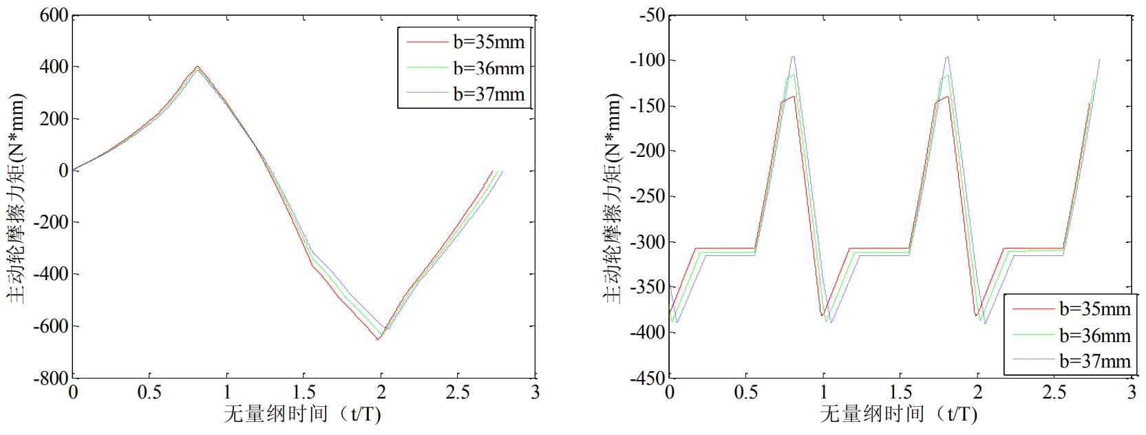
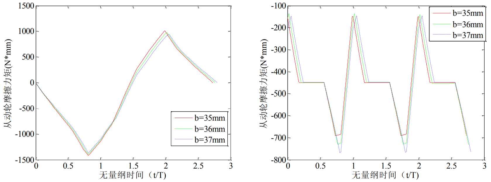
③ Influence of different contact tooth width on friction excitation:
Calculate different contact tooth widths Influence of (35mm, 36mm, 37mm) on friction excitation of helical gear system. The change of contact line length of helical gear single pair teeth and total meshing teeth in one meshing cycle is shown in FIG. 13. The single pair tooth friction and total meshing tooth pair friction of different contact tooth widths are shown in FIG. 14. With the increase of contact tooth width, the overall amplitude of friction of single pair teeth decreases; the total meshing tooth pair friction is adjusted The body amplitude increases with the increase of contact tooth width, and the holding time decreases with the increase of contact tooth width. FIG. 15 and FIG. 16 show the effects of different contact tooth widths on the single pair tooth friction of driving wheel and driven wheel and the total meshing teeth on the friction torque. With the increase of contact tooth width, the overall amplitude of the friction torque of single pair teeth decreases; The overall amplitude of the friction torque of the total meshing tooth pair increases with the increase of the contact tooth width, and the holding time decreases with the increase of the contact tooth width.