
To verify the effectiveness of the method, the method that considers the true transition curve but does not modify the upper limit of integration for different spur gear tooth numbers will be recorded as Method A; The method of considering the real transition curve and modifying the upper limit of the integration will be referred to as Method B in this article; At the same time, refer to the results obtained by the finite element method and compare the calculation results of the three methods.
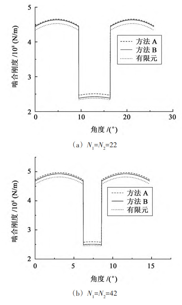
To analyze the impact of changes in the number of straight teeth on calculation errors, four sets of gears were selected: N1=N2=22; N1=N2=42; N1=N2=62; N1=19,N2=48。 Elastic modulus E=2 06 × 1011 Pa, tooth thickness L=20 mm. Figure 1 shows a comparison of the time-varying meshing stiffness calculation curves for different calculation methods under four different tooth numbers of spur gears. The specific numerical results and relative errors of the time-varying meshing stiffness calculation for the three methods are shown in the table.
| Number of teeth | Computing method | Maximum single tooth meshing stiffness/10 ^ 8 (N/m) | Relative error with method A/% | Mean value of time-varying meshing stiffness/10 ^ 8 (N/m) | Relative error with method A/% |
| N1=N2=22 | A | 2.62 | 0 | 3.56 | 0 |
| N1=N2=22 | B | 2.53 | 3.44 | 3.55 | 0.28 |
| N1=N2=22 | Finite element analysis | 2.51 | 4.20 | 3.45 | 3.09 |
| N1=N2=42 | A | 2.74 | 0 | 3.80 | 0 |
| N1=N2=42 | B | 2.64 | 3.65 | 3.76 | 1.05 |
| N1=N2=42 | Finite element analysis | 2.61 | 3.74 | 3.65 | 3.95 |
| N1=N2=62 | A | 2.73 | 0 | 3.81 | 0 |
| N1=N2=62 | B | 2.62 | 4.03 | 3.75 | 1.57 |
| N1=N2=62 | Finite element analysis | 2.60 | 4.76 | 3.66 | 3.94 |
| N1=19,N2=48 | A | 2.65 | 0 | 3.62 | 0 |
| N1=19,N2=48 | B | 2.52 | 4.91 | 3.56 | 1.66 |
| N1=19,N2=48 | Finite element analysis | 2.61 | 5.28 | 3.50 | 3.31 |
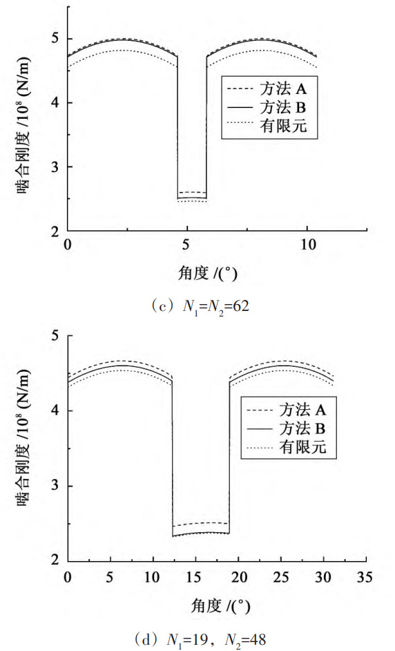
According to the formulas derived under different tooth numbers of spur gears, the calculation results show that when the tooth number of spur gears is equal to 22, the result obtained by Method A is 3 fifty-six × 108 N/m, the average time-varying meshing stiffness obtained by Method B is 3 fifty-five × 108 N/m, the results obtained by the two methods are relatively close, with a relative error of 0 28%。 This is because when the number of straight teeth is small, the starting circle radius of the involute spur gear tooth profile is similar to the base circle radius. Therefore, the difference in the average value of time-varying meshing stiffness calculation results is small. When the number of spur gears is equal to 42, the meshing stiffness value of Method A is slightly greater than that of Method B. This is because when the number of teeth in the spur gear is greater than 41, as shown in Figure 2, point Gb and point G separate, causing the actual starting point of the involute spur gear tooth profile to change. At this point, the base circle radius is smaller than the root circle radius, and the spur gear tooth model has changed. In Method A, the point Gb is still used as the upper integral limit for solving time-varying meshing stiffness, which is equivalent to taking into account the deformation energy of the GbG segment. According to equation (2), the meshing stiffness is inversely proportional to the deformation energy, so the calculation result obtained by method B is relatively small. Similarly, when the number of teeth in a spur gear is equal to 62, the calculation result obtained by Method B is also slightly smaller.
From the table, it can be seen that as the number of straight teeth increases, the relative calculation errors of the maximum single tooth meshing stiffness and the average time-varying meshing stiffness of Method A and Method B also continue to increase. This is because as the number of straight teeth increases, the starting point Gb of the involute tooth profile on the base circle gradually moves away from the starting point G of the involute straight tooth profile, and the difference between rG and rb also increases, affecting the upper limit of the integral of the involute straight tooth profile, thereby affecting the calculation results of time-varying meshing stiffness. In addition, among the three time-varying meshing stiffness calculation methods, the results of the finite element method and method B are relatively close; The relative calculation error between the finite element method and method A increases with the increase of the number of straight teeth, and has the same trend as method B, verifying the effectiveness of the proposed method.
When the number of teeth of a pair of spur gears participating in meshing is equal to 19 and 48, according to the method in this article, for the driving gear N1 with a straight tooth number less than 41, the time-varying meshing stiffness calculation formula follows the formula, and the gear tooth model is shown in Figure 3; For passive gear N2 with a straight tooth number greater than 41, the calculation formula follows the formula, and the gear tooth model is shown in Figure 2.

The calculation results indicate that the average calculation error of time-varying meshing stiffness for Method B and Method A also reaches the maximum value of 1 66%。 When calculating time-varying meshing stiffness, for a pair of teeth with a significant difference in tooth number, especially when one tooth number is less than 41 and the other tooth number is greater than 41, there may be differences in the tooth model due to different tooth numbers. If a unified model is used for calculation, it will result in significant errors.