
As the key components of power conversion between shafting transmission, helical bevel gears and hypoid gears directly affect the mechanical properties of load contact, and the geometric characteristics, processing technology and manufacturing process of helical bevel gears make the geometric accuracy control more complicated. Comprehensive analysis of the existing literature shows that the machine tool settings are tooth surface modeling, tooth surface shape error correction and tooth surface contact analysis (TCA) three major design variables for major technologies. Machine setup correction is actually an “adaptive” optimization design, where correction of the initial machine setup allows precise “data-driven” compensation for geometric accuracy caused by various errors in the manufacturing process. At present, machine tool setup correction has developed into a closed-loop system of measurement-design-manufacturing. With the application of the Universal Motion Concept (UMC), the machine setup has overcome the limitations of the previous need to design the tooth flank according to different tooth systems, machining processes and hypoboloid generators. Zhao Heng et al. proposed a tooth surface error correction method using UMC machine tool setting, which can minimize the change of rotation angle of the machine tool by the tool axis vector method, which can achieve higher and excellent machining characteristics. Wang Yanhong and others used the UMC machine tool settings to represent the generation motion of the five-axis CNC gear milling machine and carried out new teeth
Area errors are predicted and compensated online. With the emergence of new methods in the field of helical bevel gears and hypoid gears, there are also new ideas and cross-applications of machine tool setting correction technology. In addition to the compensation or correction of tooth surface errors, the synergistic optimization of the mechanical properties of load contact has also become an indispensable main content. Su Yuewen et al. will load gear contact It can be introduced into the correction that previously focused only on geometric accuracy, and a correction of hybrid machine settings that considers the coordination of shape and performance is proposed. However, establishing the relationship between machine settings and contact performance evaluation requires a great deal of numerical manipulation and optimization. In this regard, the value loads the toothed Touch analysis (NLTCA) will provide a major method, but it is very complex, DING et al. build the basic framework for co-manufacturing of helical bevel gears, taking into account the tooth surface geometry and physical properties, using closed-loop machine tool setting correction techniques, including tooth surface design, fabrication and measurement. However, the framework is limited to recently revised applications, and data-driven control has not been studied. Based on this, this paper is different from the traditional tooth surface manufacturing method that only considers the geometric accuracy of the tooth surface, and proposes an accurate double-helix milling geometric accuracy control driven by the mechanical properties of load contact to achieve collaborative optimization. Considering non-orthogonal helical bevel gears and hypoid gears, using improved TCA to solve the gear assembly problem, a new load gear contact analysis method (NLTCA) was proposed, a data-driven relationship was established, and an accurate collaborative optimization model was established considering the multi-objective optimization (MOO) of load contact mechanical property evaluation. The computational efficiency of the method.
1 Double helix milling tool design and kinematics model
Figure 1 depicts a kinematics model of a double helix milling of a non-orthogonal helical bevel gear. At each cutting point position OP, there is an additional helical motion, hence v
( c – b ) indicates the relative velocity of the tool relative to the working gear blank, which can be expressed as:
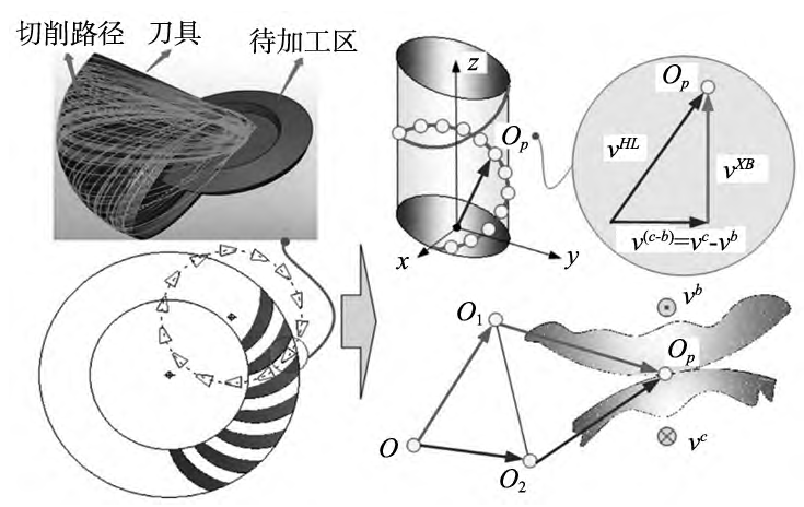
Fig. 1 Kinematics model of a double helix milling of a non-orthogonal helical bevel gear
2 Determination of initial loading contact points
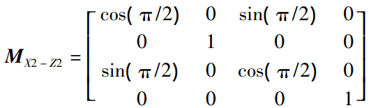
Considering the influence of small shaft angle on tooth contact performance, an improved TCA kinematics method for non-orthogonal helical bevel gears and hypoid gears is proposed. The TCA is first initialized kinematically, assuming that the pinion axis of rotation is the X2 axis, in the primary flank modeling coordinate system (X2,Y2,Z2).Located in the domain of the positive semi-axis. Similarly, the gear rotation axis is the Z1 axis, which is in the positive half-axis domain in the original tooth surface modeling coordinate system (X1,Y1,Z1). Due to the small shaft angle, the pinion rotation axis rotates 90° around the Z2 axis, and the current rotation axis is rotated to the Z2 axis, which is located in the positive semi-axis domain, and the transformation matrix is expressed as:
2.2 Solution of initial contact points
In the assembly position, the two tooth sides are very close together and there are the following geometric constraints:
2.3 Assessment and determination of TCAs
The calculation of contact points needs to be divided into:
( 1) Add iterative steps to solve positive direction contact points;
(2) Reduce the iterative steps of calculating negative directional contact points;
(3) When the contact point exceeds the actual tooth surface, complete the entire calculation;
(4) In the solution, the solved contact point within the range of the desired contact mode region ΩCP should be determined and output as the best contact point. When iteratively solving the next contact point, the design parameters of the current point are used as the basic input values. While determining the gear contact point, due to its direct data drive The functional relationship [14], the corresponding TCA evaluation can be calculated, mainly including the connection Touch path and transmission error. Figure 2 shows a flowchart for basic TCA assessment determination for non-orthogonal helical bevel gears and small shaft angle hypoid gears.
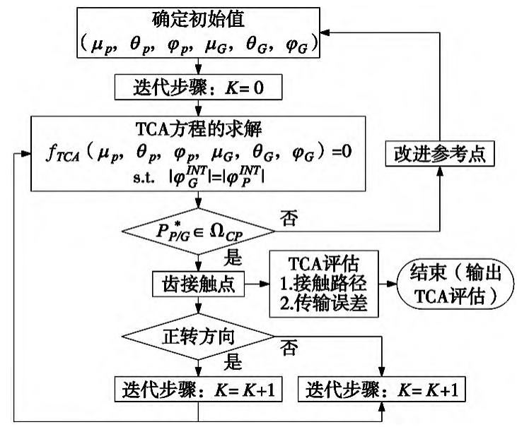
Figure 2 Improved TCA solution flowchart
3 Load contact mechanical properties of NLTCA method
In this paper, the NLTCA method based on Hertzian contact theory is used to perform double-helix milling of non-orthogonal helical bevel gears and hypoid gears, and the data-driven relationship is obtained.
3.1 Load distribution
When an input torque TIN is applied to the active gear shaft, the contact is loaded
The contact force FK at point PI – J ( θ,φ) is:
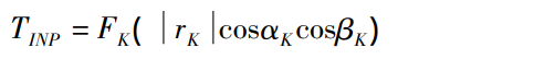
Where: z1 is the number of active gear teeth of the pinion, z2 is the number of driven gear teeth, φ1 is the rotation angle of the pinion, and the change of the rotation angle of the driven gear can be expressed by the load transmission error ( Δφ2 ) LTE. In this contact, “1” represents the first pair of contact surfaces and “2” represents the second pair of contact surfaces.
3.2 Compatibility and equilibrium conditions
When the load acts on the position distribution of each loaded tooth contact point, the tooth contact deformation calculated taking into account the tooth flexibility CK is:
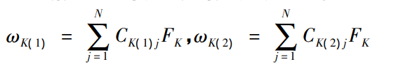
Formula: ωK( 1) is the elastic deformation of the pinion, and ωK( 2) is the elastic deformation of the gear. Figure 3 shows the data-driven matching gear contact point in the NLTCA solution, when the two helical bevel gear bodies are in the contact position, the two meshing tooth sides are truncated along the normal plane along the determined tooth contact point to obtain the two-meshing curve, PK-GK ( K = 1,2,…,N) as the target match pair of the contact point.
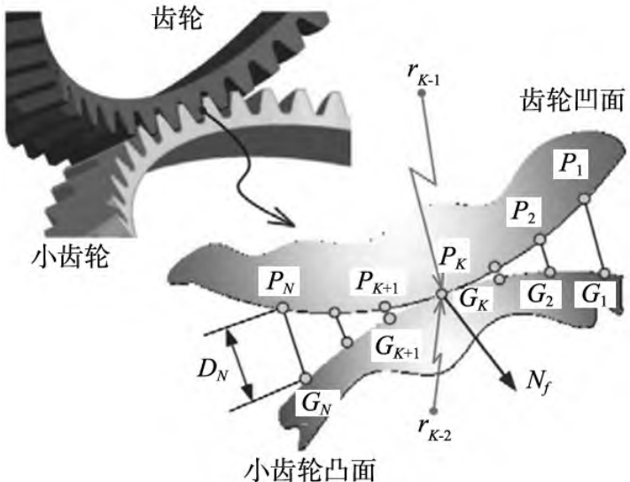
Figure 3 Matched tooth contacts in an NLTCA solution
4 Adaptive data-driven collaboration optimization
4.1 Assembly errors and data-driven design
Figure 4 is the basic definition of helical bevel gear and hypoid gear transmission assembly error [P,G,E,α], where P represents the displacement of OP in the direction of the pinion shaft, G represents the displacement of OG in the direction of the gear shaft, and E represents the two gears
The offset between shafts, α represents the angle between two gear shafts, with “+” in the positive direction and “-” in the negative direction. Exist:
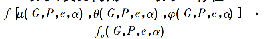
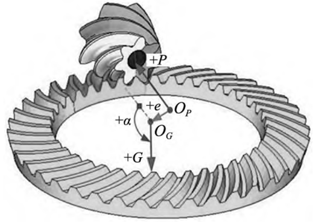
Figure 5 is a basic flowchart for adaptive data-driven co-optimization considering geometry and load contact mechanics. The number of load contact mechanical property evaluation can refer to the actual surface milling decision and gear transmission requirements, and the collaborative optimization method proposed in this paper can be used for non-orthogonal double helix milling
Helical bevel gears and hypoid gears.
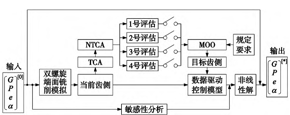
Figure 5 Basic flowchart of adaptive data-driven collaborative optimization
5 Numeric examples
Figure 6 shows data-driven modeling of the tooth flanks of a non-orthogonal helical bevel gear, including working flanks and root fillets. On the working tooth surface, tap 5 × 9 for sampling. In the root fillet workspace, tooth points are sampled at 9 × 10 to clearly indicate the bending characteristics of the tooth surface. Once the tooth flank point has been determined, it can be entered Enter the 3D drawing software, as shown in Figure 7.
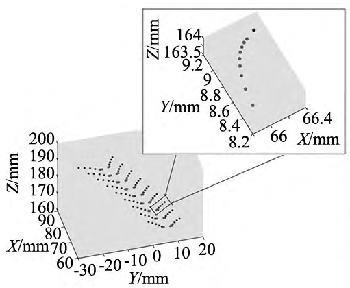
Fig. 6 Working flanks and root fillets Pinion tooth flank model
Figure 7 3D model of a non-orthogonal helical bevel gear
5.2 Contact mechanical properties
Figure 8 The size, position, and orientation of the loading contact path are defined within the constraint boundary by reference standard ANSI/AGMA 2005-D03 for the evaluation criteria determined by TCA accounting for assembly errors. It can be seen that the peak-to-peak maximum transmission error is 21. 364 μ·rad, indicating its transmission Less noise and vibration. Subsequently, after MOO was performed on the evaluation of the mechanical properties of the load contact, the NLCTA evaluation results were determined. First, considering the time-varying characteristics of the meshing division, Figure 9 determines the load contact pressure and its distribution over a cycle, where the instantaneous contact point at each moment is an approximate ellipse, and the loading contact pressure is maximum at the central loading contact point. Considering the actual situation of aviation gear transmission, this input torque is 357. 5 N·m。 The contact pressure of the load changes steadily throughout the meshing cycle.
The larger load contact pressure is mainly concentrated in the central region. at T1 =3. At 31 s, the loaded contact pressure does not have the transmission error image of edge contact and concentrated Figure 8 TCA assessment, but is evenly distributed. The maximum value is 420. 486 MPa, minimum value is 330. 852 MPa。 at T4 =3. At 46 s, the LCPMAX at the 5th loading contact point during the entire loading contact meshing process is 1 163. 10。 In T6 = 3. At the end of 56 s, the distribution is relatively uniform, and there is no edge contact and concentration.
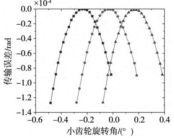
Figure 8 Transmission error evaluated by TCA
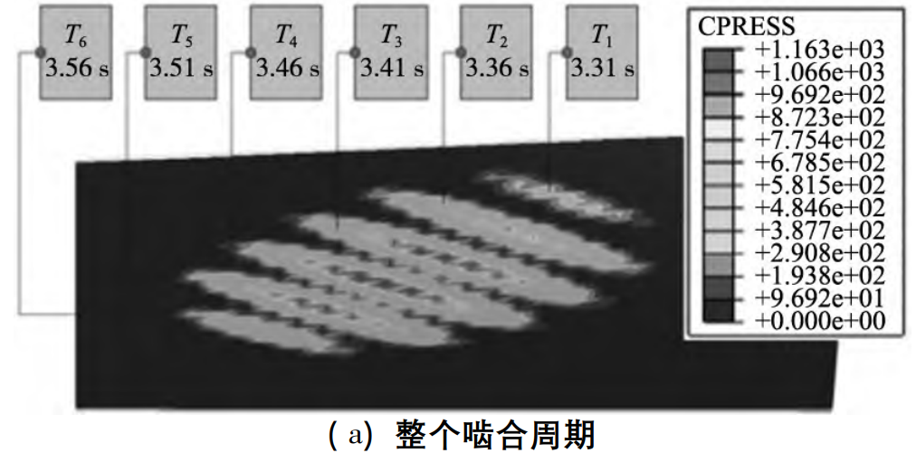
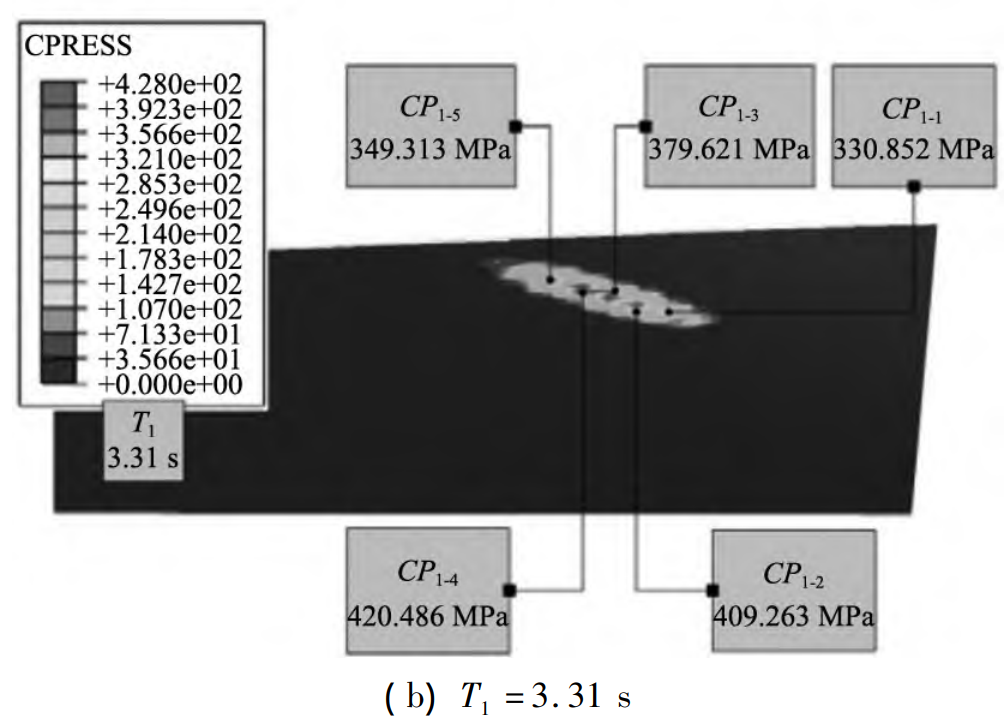
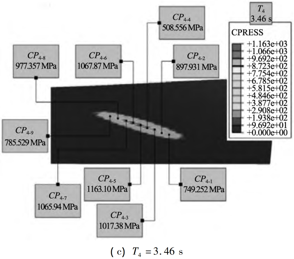
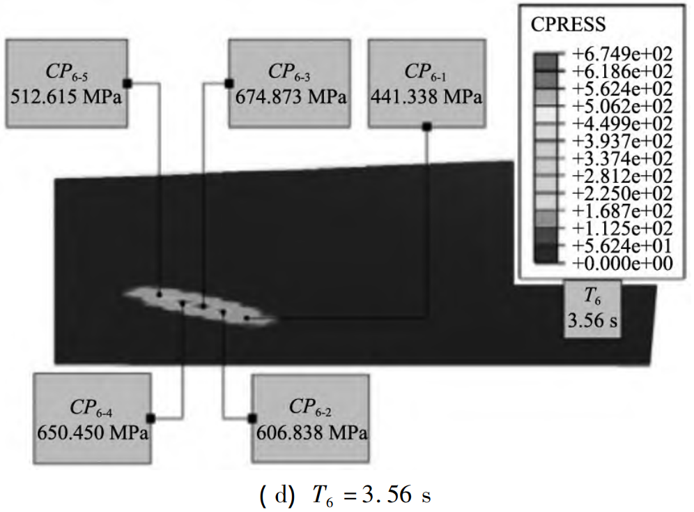
Figure 9 Load contact pressure distribution for NLTCA solving
5.3 Tooth side geometric accuracy
In the process of tooth surface geometric accuracy verification of non-orthogonal aviation helical bevel gears and hypoid gears, the main way is to optimize assembly error correction by selecting a small number of assembly error evaluations as design variables. First, determine the sensitivity factor for each assembly error assessment, as shown in Figure 10. at At 5 × 9 tooth lateral points, the sensitivity coefficient varies greatly. Compared to the mean, P has the largest sensitivity coefficient, G has the sensitivity coefficient second, followed by e and α. Therefore, P and G can be selected as the evaluation optimization design for optimal assembly error correction.
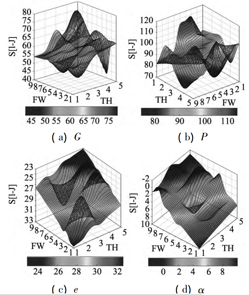
Figure 10 Assembly Error Sensitivity Factor
6 Conclusion
For non-orthogonal double helical bevel gear face milling, a collaborative optimization method based on adaptive data-driven geometry and load contact mechanical properties is proposed, and the final conclusion is as follows:
( 1) Aiming at the complex tooth surface geometry of non-orthogonal helical bevel gears and hypoid gears, double helix milling is used for simulation modeling, and an improved TCA is proposed to solve the gear assembly problem.
(2) The load gear contact analysis method (NLTCA) was used to determine the data-driven relationship between load contact mechanical property evaluation and assembly error, and the multi-objective optimization of load contact mechanical property evaluation was considered
(MOO), by correcting the assembly error evaluation, an adaptive data-driven collaborative optimization model is established.
( 3) The adaptive data-driven collaborative optimization decision-making process is divided into two subsystems: on the one hand, when the target tooth surface is determined by multi-objective optimization (MOO) of load contact mechanical property evaluation, the Pareto optimal solution is obtained by the degree of achievement function method, and on the other hand, the tooth surface geometry is optimized by assembly error correction
, and sensitivity analysis strategies are used to select the best design variables. This optimization strategy can improve the efficiency of the entire adaptive data-driven optimization process.