1. Introduction
Coaxial double-output cylindrical gear split-combined-torsion transmission systems are widely used in aerospace, marine engineering, and heavy machinery due to their compact structure, lightweight design, and high load-bearing capacity. However, despite their inherent symmetry in configuration, uneven load distribution among transmission branches remains a critical challenge. This study investigates the impact of meshing phase differences on the static load-sharing characteristics of such systems, focusing on cylindrical gears.

1.1 Background and Motivation
Cylindrical gears are fundamental components in power transmission systems. In coaxial configurations, dual-output shafts must distribute torque evenly to ensure reliability and minimize wear. Previous studies have explored dynamic behaviors and load-sharing mechanisms in split-torque systems, yet the role of meshing phase differences under static conditions remains underexplored. This research bridges this gap by analyzing how phase mismatches between gear pairs affect load distribution.
2. Static Analysis Model
2.1 System Configuration
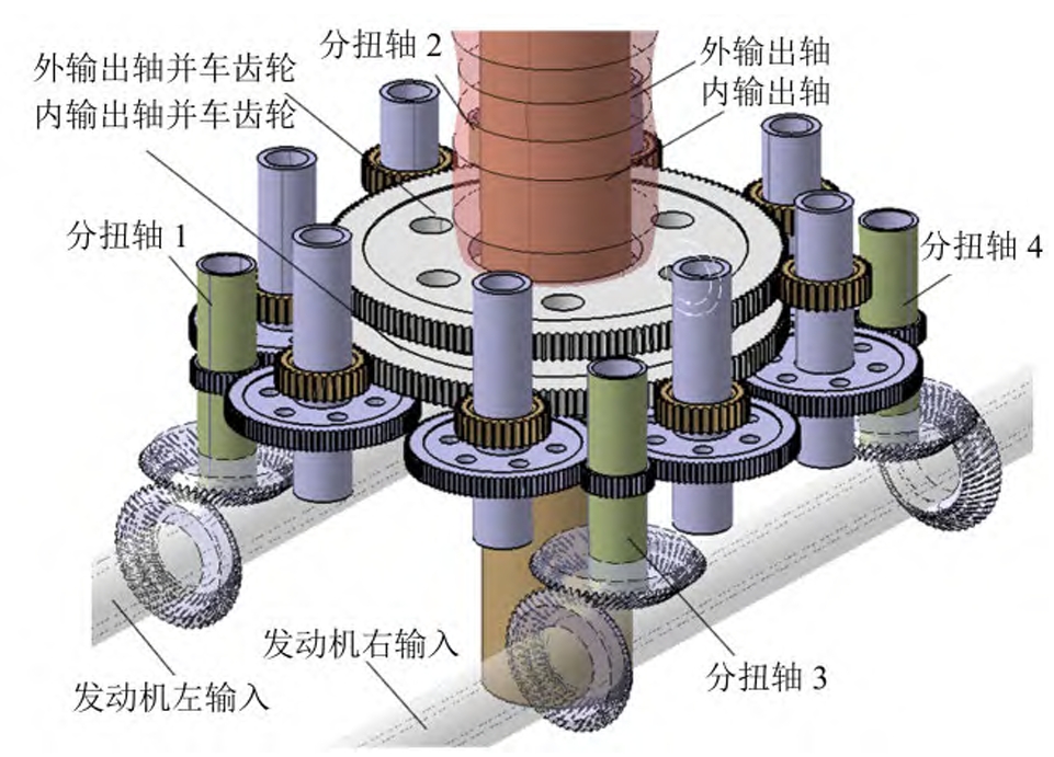
The transmission system comprises two input paths and coaxial dual-output shafts. Each input path drives a split-torsion stage, which then transfers power to a combined-torsion stage. The cylindrical gears in these stages are critical for torque distribution.
2.2 Key Parameters
The cylindrical gear parameters for split-torsion and combined-torsion stages are summarized below:
| Parameter | Split-Torsion Stage | Combined-Torsion Stage |
|---|---|---|
| Module (mm) | 2.4 | 3.7 |
| Number of Teeth | 36 (Driver) / 100 | 31 (Driver) / 159 |
| Face Width (mm) | 25 | 35 |
| Pressure Angle (°) | 20 | 20 |
| Elastic Modulus (MPa) | 2.1×10⁵ | 2.1×10⁵ |
| Poisson’s Ratio | 0.3 | 0.3 |
3. Governing Equations
3.1 Static Equilibrium Equations
The static equilibrium conditions for the cylindrical gear system are derived from torque balance and deformation compatibility:
- Torque Balance:{Ta1−Ta2=0Ta1+Ta2−i1Ta1=0Ta1−Ta2=0Ta1−i2∑i∑jTa1=0⎩⎨⎧Ta1−Ta2=0Ta1+Ta2−i1Ta1=0Ta1−Ta2=0Ta1−i2∑i∑jTa1=0where Ta1,Ta2Ta1,Ta2 are gear torques, and i1,i2i1,i2 are transmission ratios.
- Force Balance:{Tki1srbscosαki1p+Tki2srbscosαki2p−Kkipxxkip=0Tki1srbssinαki1p+Tki2srbssinαki2p−Kkipyykip=0{Tki1srbscosαki1p+Tki2srbscosαki2p−Kkipxxkip=0Tki1srbssinαki1p+Tki2srbssinαki2p−Kkipyykip=0Here, Kkipx,KkipyKkipx,Kkipy represent support stiffness, and xkip,ykipxkip,ykip denote gear displacements.
3.2 Deformation Compatibility
Gear meshing deformations and shaft torsional displacements are modeled using:ϕkij=i1(ϕkij1+ϕkij2+ϕkij3)+ϕkij4+ϕkij5ϕkij=i1(ϕkij1+ϕkij2+ϕkij3)+ϕkij4+ϕkij5
where ϕkij1,ϕkij2ϕkij1,ϕkij2 account for gear pair deformations, and ϕkij3ϕkij3 represents shaft twist.
4. Meshing Phase Difference and Load Sharing
4.1 Definition of Phase Difference
Meshing phase difference (γγ) arises when two gear pairs engage at mismatched timings due to manufacturing tolerances or assembly errors. For cylindrical gears, this difference alters the instantaneous meshing stiffness, leading to uneven load distribution.
4.2 Time-Varying Meshing Stiffness
The meshing stiffness of cylindrical gears is calculated using the potential energy method:k=∑i=1n(1kh,i+1kb1,i+1kb2,i+⋯ )−1k=i=1∑n(kh,i1+kb1,i1+kb2,i1+⋯)−1
where kh,ikh,i, kb1,ikb1,i, and kb2,ikb2,i denote Hertzian, bending, and shear stiffness, respectively.
4.3 Impact of Phase Difference
Table 2 summarizes the relationship between phase difference and load-sharing coefficient (ΩΩ) for inner and outer output shafts.
| Phase Difference | Load Sharing Coefficient (ΩΩ) | Fluctuation Amplitude |
|---|---|---|
| 0° | 1.02 (Inner) / 1.01 (Outer) | ±0.05 |
| +15° | 1.18 (Inner) / 1.12 (Outer) | ±0.21 |
| -15° | 1.22 (Inner) / 1.15 (Outer) | ±0.25 |
Key observations:
- Larger phase differences degrade load-sharing performance.
- Combined-torsion stages are more sensitive to phase mismatches than split-torsion stages.
- Inner output shafts exhibit higher sensitivity to right-input phase differences, while outer shafts are affected more by left-input mismatches.
5. Optimization Strategies
To mitigate phase difference effects in cylindrical gear systems:
- Tolerance Control: Minimize manufacturing errors in gear tooth profiles and assembly misalignments.
- Stiffness Matching: Optimize shaft torsional stiffness to balance deformation-induced phase shifts.
- Phase Compensation: Introduce deliberate phase offsets (e.g., negative phase for inner shafts) to counteract natural mismatches.
6. Conclusion
This study establishes a static analysis framework for coaxial double-output cylindrical gear systems, revealing that:
- Meshing phase differences significantly degrade load-sharing uniformity.
- Combined-torsion stages are more vulnerable to phase mismatches.
- Directional sensitivity exists between inner and outer output shafts.
By integrating stiffness calculations, deformation models, and phase difference analysis, this work provides actionable insights for designing robust cylindrical gear transmissions.
