
1 Determination of process plan
1.1 Analysis of part structure characteristics
Figure 1 is the part diagram of a planetary gear of a truck with two parts, internal bore and external teeth, and its tooth profile parameters are shown in Table 1.
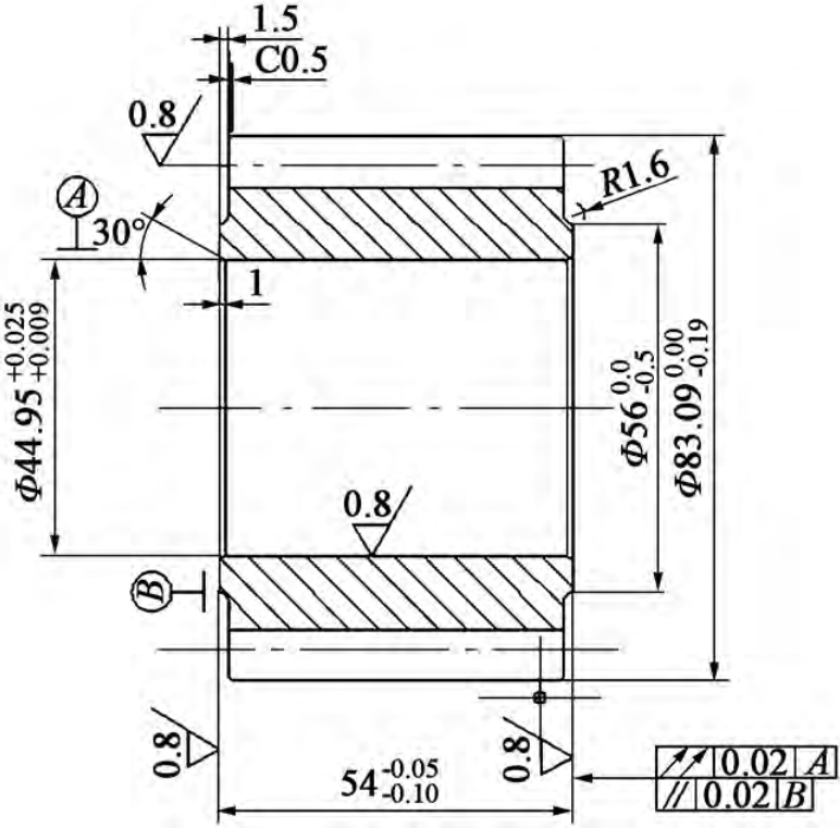
Figure 1 Component diagram of a planetary gear for a truck with a truck
Table 1 External gear parameters of planetary gears for a truck
| 参数 | 齿数 z | 模数 m | 压力角 αn / (°) | 变位系数 x |
| 数值 | 18 | 4.1 | 22.5 | +0. 366 |
1.2 Analysis of cold extrusion forming process
At present, through-type positive extrusion planetary gears are a more commonly used cold extrusion method, and the required forming load is about 3500 kN Hollow blanks are usually taken by hot forging. Figure 2a shows the forming process of through-type positive extrusion, the inner hole of the blank is constrained, and the punch is forced to move the hollow blank downward under the action of the press, which is formed in the forming area of the die shape external teeth, but due to the long process route, high energy consumption during hot forging, and the hollow blank needs to be reprocessed after hot forging, resulting in large material consumption and increased cost. Therefore, this paper proposes a process scheme of cold extrusion forming through solid billet to solve the problem of low material utilization and high cost, as shown in Figure 2b, the upper convex die moves downward during extrusion.
The solid blank is forced through the cavity of the die and the down-convex die, and the inner hole and the outer tooth are formed simultaneously under the action of the sizing belt. The material utilization rate of the conventional hollow billet forming planetary gear process solution is about 70%,
Compared with the traditional through-through scheme, this scheme saves the related processes of hot forging hollow blank, significantly reduces energy consumption and reduces production costs.
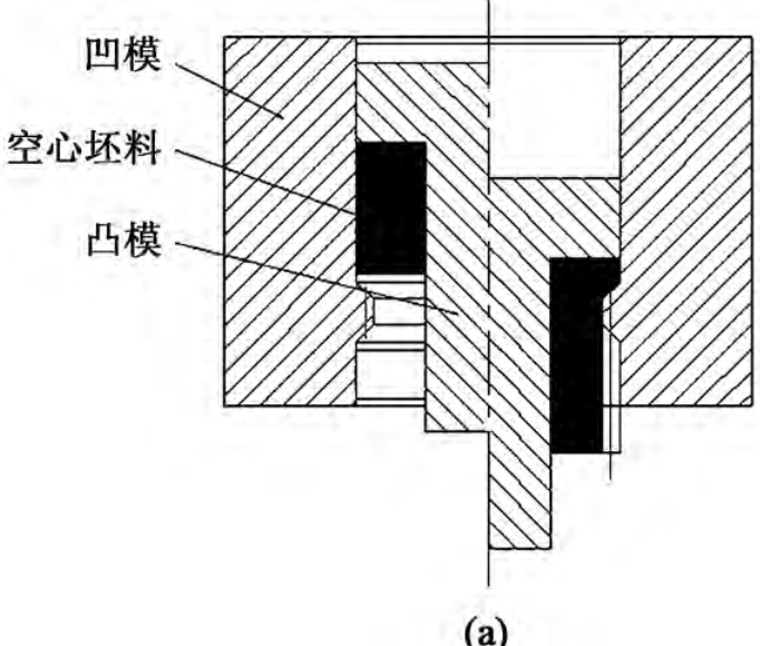
Figure 2 Comparison of cold extrusion process solutions
2 Finite element simulation and analysis
2.1 Finite element modeling
In this paper, according to the cold extrusion process scheme of planetary gears, the three-dimensional model is established by UG software, and the simulation analysis is carried out with the help of DEFORM-3D finite element software, and the half angle of the die inlet mouth is α, and the length of the die sizing belt is H, the top angle of the lower convex cone is γ. The created 3D model is saved in STL format and imported into the DEFORM-3D software for parametric settings, because the planetary gear is symmetrical, in order to save simulation time, it is selected The gear 1/18 is simulated, and the friction factor is set to 0. 12, The friction type is shear friction, the movement speed of the upper convex die is 20 mm·s-1, the temperature is 20 °C, the blank material is 20CrMnTi steel, the mechanical properties of the material are shown in Table 2, the number of meshes is set to 20000, and Figure 3 is the established finite element geometry model. In DEFORM-3D software, rigid-plastic finite element simulation and elastoplastic finite element simulation can be carried out, because the elastoplastic finite element model has higher computer requirements and slower operation rate, it is generally used for mold stress analysis and failure analysis, and there are many simulation examples for the combination of process parameters in this paper, and the operation speed requirements are higher, so rigid-plastic finite element simulation is more appropriate. Here the mold is set to a rigid body, and the blank is set to a plastic body.
Table 2 Mechanical properties of 20CrMnTi steel
| 参数 | 数值 |
| 泊松比 | 0.25 |
| 屈服强度/ MPa | 835 |
| 抗拉强度/ MPa | 1080 |
| 弹性模量/ GPa | 207 |
| 伸长率/ % | 10 |
2.2 Analysis of numerical simulation results
According to the actual experience, in the cold extrusion forming process, the half angle of the die into the die mouth, the length of the die sizing belt and the top angle of the lower convex die cone have a great influence on the forming quality and forming load.
2.2. 1 Influence of die inlet half angle α on metal flow law
In cold extrusion forming, under the action of the press, the die into the die mouth plays a guiding role on the blank, in order to explore the die into the die mouth half The metal flow law of angle pair planetary gear forming was selected α = 20°, 30°, 40°, 50°, 60°, 70° and 80° for numerical simulation, in order to ensure the consistency of parameters, H = 12 mm, γ = 12°. Figure 4 shows the collapse angle of the outer teeth when the half angle of the die mouth is 20°, 40° and 60°, and it can be seen from Figure 4 that the collapse angle of the lower end of the outer teeth under the half angle of the die mouth of different dies is different. Figure 5 shows the variation trend of the collapse angle of the lower end of the outer tooth under the half-angle of different dies into the die mouth. It can be seen from Figure 5 that when the half angle of the die inlet mouth is less than 50°, the reduction rate of the collapse angle is large, which is due to the die in When the half angle of the die mouth is small, the outer metal is more prone to axial flow, resulting in excessive flow rate difference between the inner and outer metal layers, which has a greater impact on the collapse angle and the collapse angle phenomenon is significant. When the half angle of the die into the die mouth is greater than 50°, the collapse angle reduction speed is not obvious, which is because the metal is prone to radial flow when the large die enters the die mouth half angle, resulting in little difference between the internal and external speeds, right The influence of collapse angle is small, so it is not easy to collapse phenomenon.
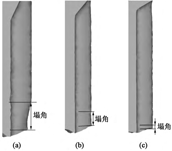
(a) α= 20° (b) α= 40° (c) α= 60°
Figure 4 α The length of the collapse angle at the lower end of the outer tooth when different values are taken
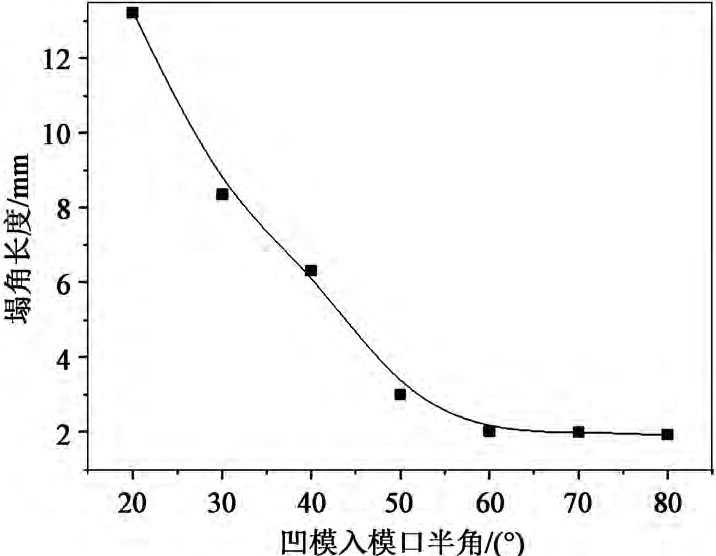
Figure 5 Trend plot of collapse length with α value
Figure 6 is the motion vector diagram of the extrusion when the half angle of the die mouth is 20°, 40°, 60°, and the black line is the constant velocity line, which shows the axial and radial flow of the metal under the action of the lower convex die and the concave die forming area during the extrusion process. According to the principle of volume invariance and the principle of the movement of the blank in the direction of minimum resistance during the extrusion process, it can be seen that the flow state of the blank at the half angle of the die mouth of different dies is also different. When the die entry mouth half angle is 20°, the outer gold The flow velocity is fast, and the internal metal flow speed is slower, resulting in inconsistent internal and external rates, and obvious collapse angle phenomenon, as shown in Figure 6a. When the half angle of the die inlet mouth is 40°, the half angle of the die inlet mouth increases, and the outer metal flow tends to radial, so the internal and external velocity difference decreases, and the collapse angle defect is improved, as shown in Figure 6b. When the half-angle of the die entrance is 60°, the constant velocity line approaches the horizontal, indicating that the difference between the internal and external velocity is close to 0, and there is no obvious collapse phenomenon, as shown in Figure 6c.
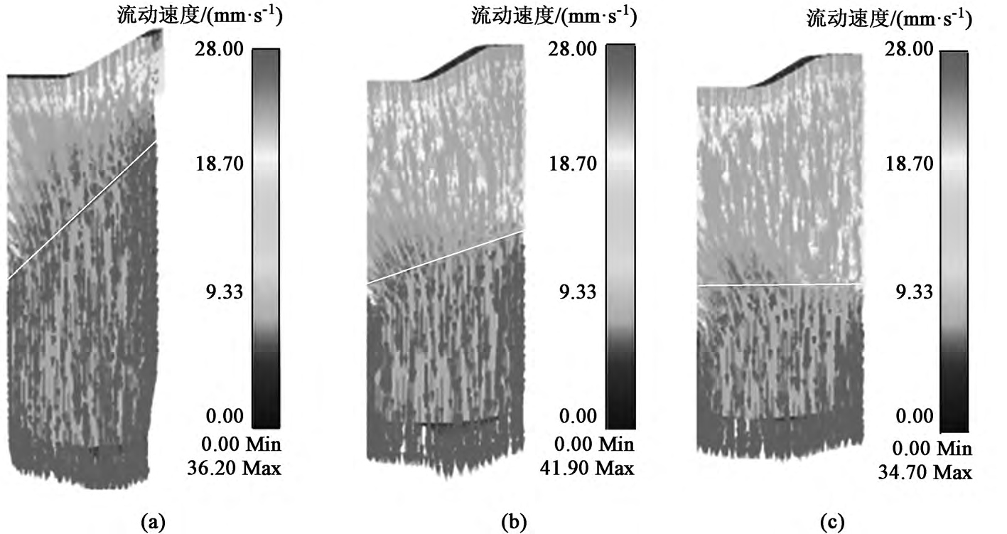
Figure 6 α Vector plot of velocity of extrusions when different values are taken
Figure 7 shows the shrinkage of the upper end of the outer tooth when the half-angle of the die entrance is 20°, 40°, 60° and 80°, and the stop condition is 3 mm fixed (the stop condition refers to the axial distance between the top end of the upper convex die and the top of the lower convex die).
It can be seen that the half angle of the die inlet has an effect on the shrinkage hole, and the overall trend is that it decreases with the increase of the half angle of the die inlet mouth. When the half angle of the die into the die mouth is 20° ~40°, the shrinkage defect at the upper end is significant, and when the half angle of the die into the die mouth is 40° ~ 60°, the shrinkage hole defect is improved, when concave
When the half-angle of the mold mouth is 60° ~ 80°, the shrinkage defect is not obvious. Figure 8 shows the forming load trend under the half angle of different die inlet ports, and it can be seen from Figure 8 that as the die inlet half angle increases, it The required forming load also increases, because when the half angle of the die into the die is too large, the metal is not easy to occur axial flow, then in order to overcome the axial resistance of the die inlet shunt, more forming force is required to participate, so the excessive die half angle should not be selected. In summary, if the half angle of the die into the die is too small, the upper end shrinkage hole and the lower end collapse angle will be generated, and when the half angle of the die into the die is too large, a large forming load will be generated, so the α is selected as 60° for comprehensive consideration.
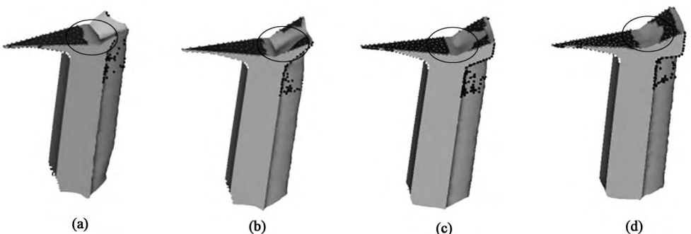
Figure 7 α Shrinkage holes at the upper end of the outer teeth when different values are taken
2.2. 2 Effect of die sizing belt length H on metal flow law
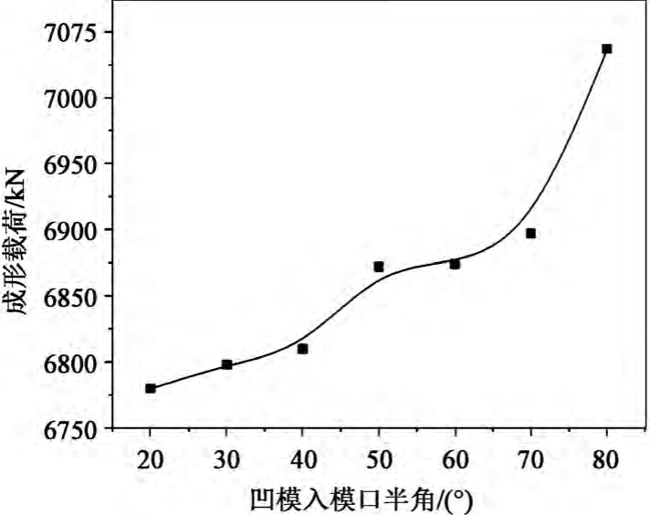
Fig. 8 α Forming load curves with different values
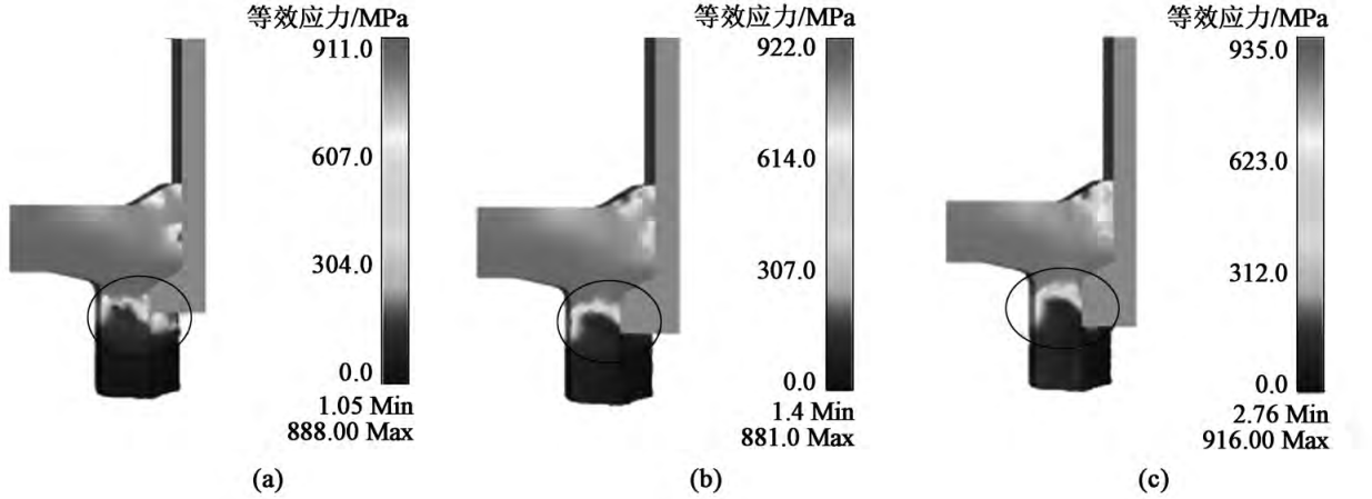
Figure 9 H Equivalent force cloud with different values
In the cold extrusion forming process, the die sizing belt plays a limiting role in the plastic deformation zone of the blank, and the appropriate die sizing belt length will greatly reduce the forming defects, in order to explore the length of the die sizing belt on the planetary gear The influence law of forming quality, in order to lay the foundation for the selection of suitable process parameters, H = 3, 6, 9, 12 and 15 mm were selected for numerical simulation analysis, in order to ensure the consistency of parameters, set α= 60°, γ = 12°.
Figure 9 shows the equivalent force cloud diagram when the length of the die sizing band is 6, 9 and 12 mm, it can be seen that when the length of the die sizing band is less than 9 mm, the plastic transformation zone cannot be completely limited, and the blank will be sent after molding
Irregular deformation will greatly affect the forming quality; When the length of the die sizing belt is greater than 9 mm, the plastic deformation zone can already be limited, and no large irregular deformation will occur. Therefore, in order to ensure the forming quality of the planetary gear, the length of the die sizing belt should be greater than the length of the plastic deformation zone. Figure 10 shows the influence curve of the length of the sizing belt of the die on the forming load, from which it can be seen that the length of the sizing band increases from 3 ~ 15 mm In the long process, the forming load shows a slow increase trend, because the longer the length of the die sizing belt, the greater the friction, so the required forming force is also greater.
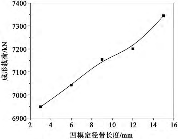
Fig. 10 H Maximum forming load curve with different values
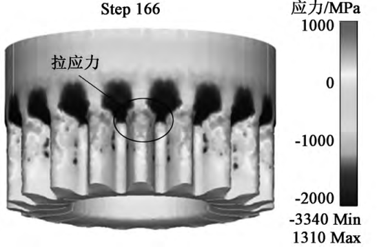
Fig. 11 Surface tensile stress when the length of the die sizing belt is too large
If the length of the die sizing belt is too long, in addition to increasing the forming load, it will also cause tensile stress on the surface of the extrusion, as shown in Figure 11. The generation of tensile stress is the main reason for cracking on the surface of the extrusion, so it should be avoided as much as possible, the longer the length of the die sizing belt, the larger the range of tensile stress, and the easier it is to produce tensile stress. For molds, yes Destroy the phosphating saponification layer, resulting in mold sticking, thereby affecting the mold life; For extruded parts, cracks will occur on the tooth surface, which will affect the quality of the formed tooth profile. In summary, when selecting the length of the concave die sizing belt, it is necessary to completely limit the plastic deformation zone, and avoid excessive tensile stress and excessive forming load, and it is more appropriate to select the length of the concave die sizing belt of 12 mm.
2.2. 3 Influence of the top angle of the lower convex cone γ on the flow law of metal
In the cold extrusion process, the lower convex die plays the role of shunt forming for the inner hole of the planetary gear in one forming, and the cone top angle of the lower convex die is used as an important parameter of the lower convex die, and the appropriate cone top angle will reduce the forming defects. In order to study its influence on the formation of planetary gears, γ = 4°, 8°, 12°, 16° and 20° were selected for numerical simulation analysis, and in order to ensure the consistency of the parameters, α= 60°, H= 12 mm were set. Fig. 12 shows the shrinkage under the top angle of the cone of the lower convex die at a stop condition of 3 mm, as can be seen from Figure 12, with the lower convex die
With the increase of the cone top angle, the shrinkage defect is gradually improved.
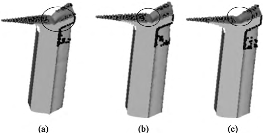
Figure 12 γ Shrinkage holes at the upper end of the outer teeth when different values are taken
According to experience, the appearance of shrinkage holes is also related to the thickness of the upper end of the extrusion, and the thinner the upper end extrusion, the more likely it is to shrink holes.
In order to study the thickness of the upper end of the extrusion under the condition of shrinkage hole defects under different conditions of the top angle of the conical cone of the lower convex die, the numerical simulation was carried out respectively, and the change trend shown in Figure 13 was obtained. According to the numerical simulation results, it can be seen that with the increase of the top angle of the lower convex cone of the lower convex die, the thickness of the upper end of the extrusion decreases, and the extrusion thickness decreases The thinner the degree, the higher the utilization rate of the material, so the top angle of the lower convex cone should not be too small. Figure 14 shows the influence curve of the top angle of the lower convex die cone on the forming load, it can be seen that the forming load decreases with the increase of the top angle of the lower convex die cone, and when the top angle of the lower convex die cone is 4° ~ 8°, the forming load decreases rapidly When the top angle of the punch cone is 8° ~ 20°, the forming load decreases slowly. In summary, the selection of the top angle of the lower convex cone should be fully considered For the effects of shrinkage holes and forming loads, 12° is more suitable in this article.
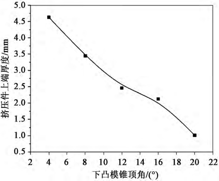
Figure 13 Trend chart of the thickness of the upper end of the extrusion with γ
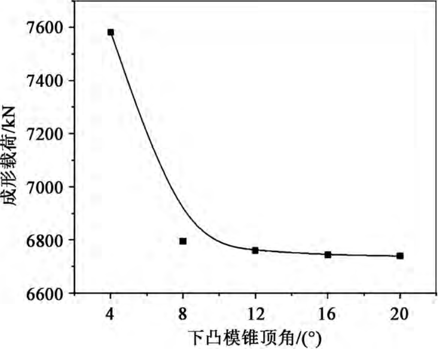
Fig. 14 Curve of forming load vs. γ
3 Process test
According to the numerical simulation results, the process test parameters are shown in Table 3, the mold is manufactured according to the parameters, Cr12MoV steel is selected for the upper and lower punch materials, and YG20 cemented carbide is selected for the die core,The actual mold is shown in Figure 15.
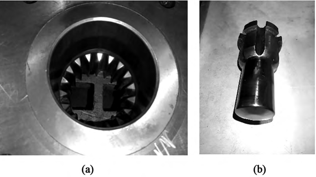
Figure 15 Actual mold drawing
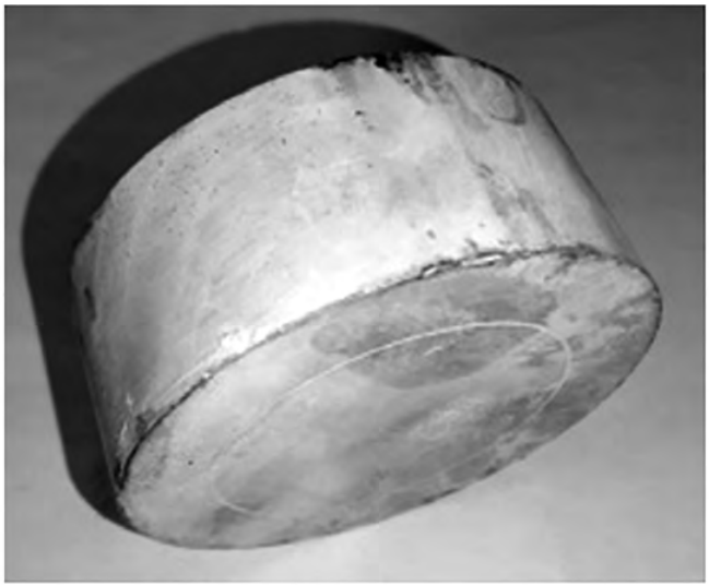
Figure 16 Solid blank
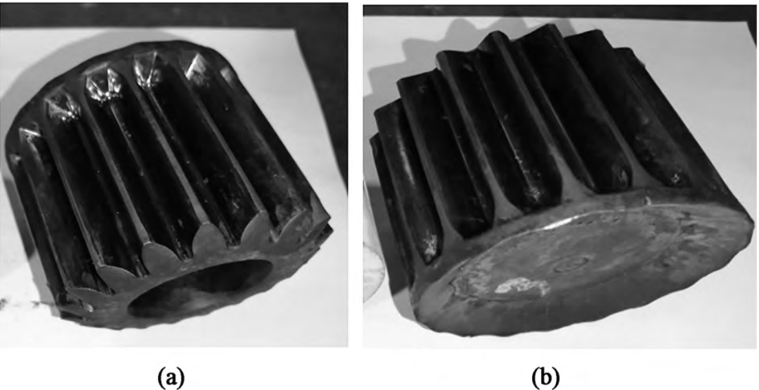
Figure 17 Cold extrusion physical drawing
Fig. 16 shows the solid blank tested by the process, annealed and phosphating saponification before extrusion, and Fig. 17 shows the extruded part formed by a cold extrusion process. This is available in Figure 16 and Figure 17After forming, it can be seen that the tooth shape is full, the whole has no obvious defects, the surface quality is good, and the maximum forming force of the project is 6202 kN after the equipment, and the numerical simulation result is 6840 kN, the actual value and simulation
The value is within the error range, which meets the forming requirements, which confirms the feasibility of the scheme.
4 Conclusion
(1) According to the existing hollow billet forming planetary gear scheme, a one-time cold extrusion forming process scheme through solid billet is proposed
Process trials have proved the feasibility of this scheme.
(2) When the half angle of the die into the die mouth is small, the formation speed difference inside and outside the extrusion is different, the more obvious the collapse angle phenomenon, the more significant the shrinkage phenomenon at the upper end.
However, when the half angle of the die inlet mouth is too large, the forming load will increase. Therefore α 60° is more appropriate.
(3) When the length of the die sizing belt is too long, the forming load will be increased, and at the same time, excessive tensile stress will be generated on the surface of the blank due to the increase of friction area, resulting in strain, sticking mold and other phenomena. Therefore, H is 12 mm better
for fit.
(4) When the stopping condition is 3 mm, the shrinkage defect is gradually improved with the increase of the top angle of the lower convex cone of the lower convex die. With the lower convex cone With the increase of the top angle, the thickness of the upper end of the extrusion decreases. When the top angle of the punch cone is too small, a large forming load will be generated. Therefore γ 12° is more appropriate.
(5) The forming load of the primary cold extrusion forming process scheme is larger than that of the through-type cold extrusion forming scheme, and the mold requirements are higher.