
In the field of mechanical transmission, the straight spur gear remains a fundamental component. Traditional machining methods for straight spur gear, such as hobbing and shaping, suffer from low material utilization, high production cost, and poor fatigue strength due to the severance of metal fibers along the tooth profile. To overcome these limitations, cold forging has emerged as a promising near‑net‑shape process. Compared to hot forming, cold forging yields superior dimensional accuracy, excellent surface finish, increased strength through work hardening, and significantly higher material utilization. Moreover, it eliminates the need for heating, reduces energy consumption, and enables a favorable metal flow pattern that enhances the load‑bearing capacity of the straight spur gear.
This work focuses on the cold forging of a cylindrical straight spur gear using a combined axial‑relief and floating‑die coupling technique. The process is analyzed by means of finite element numerical simulation (DEFORM‑3D). The investigation aims to reveal the evolution of effective strain, effective stress, velocity field, and forming load during the cold forging process. The results provide a theoretical basis for the practical application of this technique.
Finite Element Model Establishment
The straight spur gear studied in this work has the following geometric parameters:
| Parameter | Symbol | Value |
|---|---|---|
| Module | \(m\) | 2 mm |
| Number of teeth | \(Z\) | 18 |
| Face width | \(h\) | 10 mm |
| Normal pressure angle | \(\alpha\) | 20° |
| Profile shift coefficient | \(x\) | 0.0 |
| Central relief hole diameter | \(d\) | 10 mm |
The billet is a cylinder. According to the principle of volume constancy during cold forging and considering a small allowance for subsequent finishing, the billet dimensions are determined as \(\phi 30\ \text{mm} \times 15\ \text{mm}\). Owing to the geometric symmetry of the straight spur gear, only one quarter of the full model is taken as the simulation domain to reduce computational cost. The three‑dimensional geometry of the upper die, floating die, and lower die is created in CAD software, and the assembly is imported into DEFORM‑3D. The billet is meshed with tetrahedral elements.
The image below illustrates a typical straight spur gear produced by cold forging:
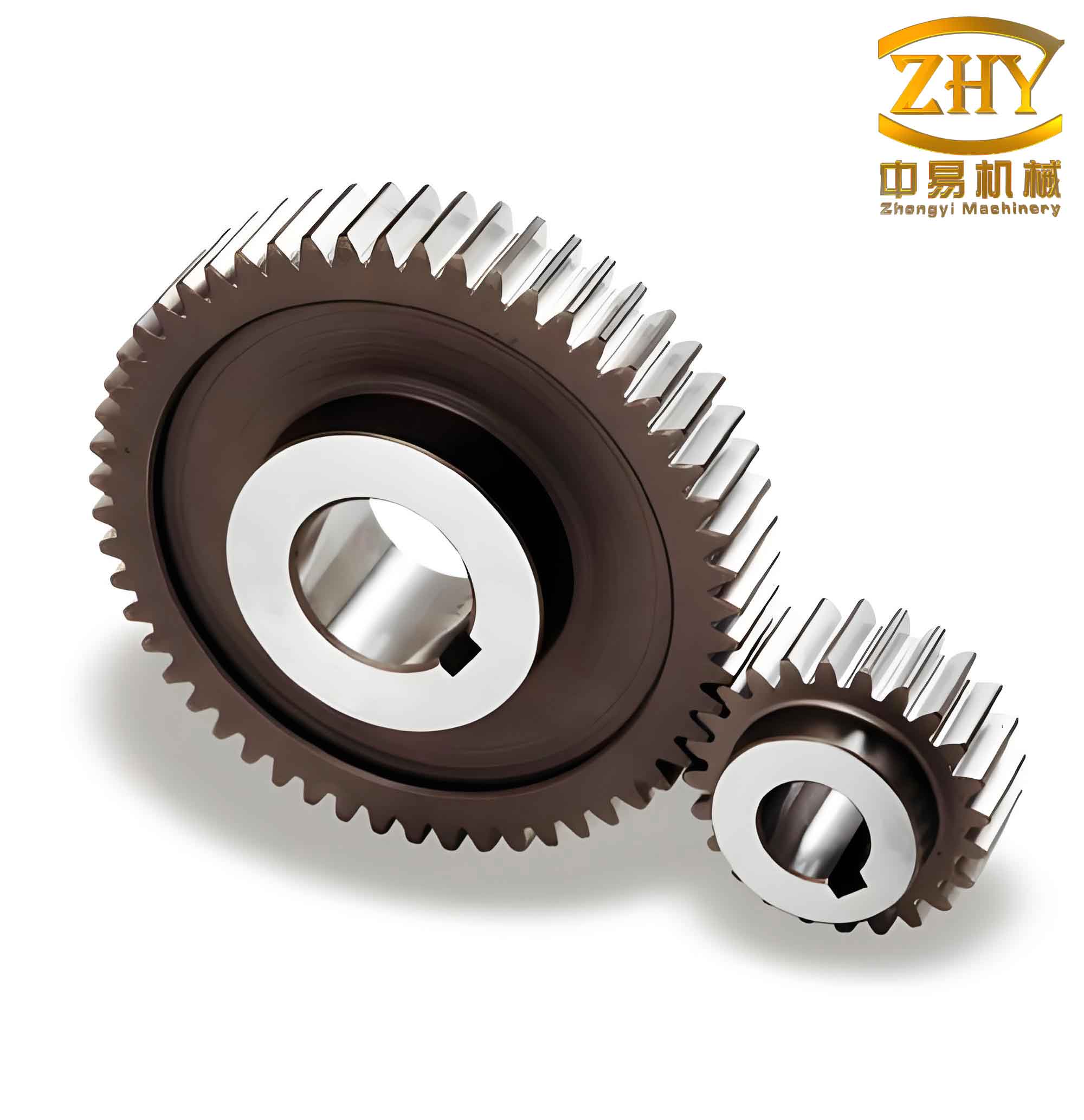
Table 2 summarizes the key simulation parameters:
| Parameter | Value / Description |
|---|---|
| Billet material | AISI‑4140 (cold) |
| Billet behavior | Plastic |
| Die behavior | Rigid |
| Friction type | Shear friction |
| Friction coefficient | 0.12 |
| Upper die speed | 1 mm/s |
| Floating die speed | 1 mm/s |
| Mesh type | Tetrahedral |
| Symmetry | 1/4 model |
It is worth noting that the floating die moves together with the upper die at the same velocity. This coupling, together with the axial‑relief hole in the center, facilitates material flow into the tooth cavities and reduces the final forging load.
Numerical Simulation Results and Discussion
Effective Strain Distribution
During the cold forging of the straight spur gear, the effective strain \(\bar{\varepsilon}\) is given by
\[
\bar{\varepsilon} = \sqrt{\frac{2}{3} \varepsilon_{ij} \varepsilon_{ij}}
\]
where \(\varepsilon_{ij}\) are the components of the logarithmic strain tensor. The simulated effective strain distribution at different deformation stages reveals that the tooth region undergoes significantly larger strain than the central shaft region. Specifically, the strain concentrates in the tooth cavity and at the corner regions between the upper/lower die and the tooth form. At the final filling stage, almost the entire tooth volume exhibits high effective strain, indicating severe plastic deformation that contributes to grain refinement and strength enhancement.
Table 3 lists the approximate maximum effective strain values at three representative stages:
| Stage (increment step) | Maximum effective strain |
|---|---|
| 60 | 1.2 |
| 75 | 2.8 |
| 89 | 4.5 |
Effective Stress Distribution
The effective stress \(\bar{\sigma}\) (von Mises stress) is defined as
\[
\bar{\sigma} = \sqrt{\frac{3}{2} s_{ij} s_{ij}}
\]
where \(s_{ij}\) is the deviatoric stress tensor. In the simulation, the central relief hole region exhibits the lowest effective stress, while the tooth region experiences high stress levels. A high effective stress is beneficial for healing internal micro‑defects and damages in the material. The stress distribution correlates well with the strain distribution: regions of large deformation are accompanied by high stress. At the final stage, the effective stress in the tooth cavity reaches values close to the flow stress of AISI‑4140 at room temperature.
The following table summarizes the average effective stress in the tooth region at different increments:
| Increment step | Average effective stress (MPa) |
|---|---|
| 60 | 450 |
| 75 | 680 |
| 89 | 920 |
Velocity Field
The velocity distribution during the forging process directly indicates material flow direction. In the early stage of deformation, the resistance for material flowing into the tooth cavity is smaller than that for flowing into the central hole; therefore, the velocity vectors point predominantly toward the tooth cavities. Owing to the floating die, an axial force component assists the filling of the lower tooth tip. Since the upper die moves downward while the lower die remains stationary, the velocity in the upper half of the billet is greater than that in the lower half. In the final stage, when the tooth cavities are nearly filled, the material in the central hole region experiences a lower stress state (mainly bi‑axial compression) compared to the tooth region (tri‑axial compression). Consequently, the material flow toward the central hole becomes dominant. This observation underscores the role of the axial‑relief hole in releasing excessive pressure and preventing die failure.
Table 5 gives the maximum velocity magnitude in the workpiece at three steps:
| Increment step | Max velocity (mm/s) |
|---|---|
| 60 | 1.8 |
| 75 | 1.5 |
| 89 | 2.2 |
Forming Load – Displacement Curve
The load‑displacement curve (Figure 6 in the original study) reveals four characteristic phases. Initially, the upper die contacts the billet and the load rises linearly. This is followed by a nearly flat region corresponding to the upsetting of the billet, where the load increases slowly and the forming force is relatively low. When the billet starts to enter the tooth cavities, the load rises more steeply because of the increasing contact area and the constrained flow. As the upper die continues to descend, more material flows into the die cavities and a small amount enters the central relief hole; the forming force grows moderately. Finally, when the tooth cavities are almost completely filled, the load increases dramatically while the displacement increment becomes very small. This terminal stage corresponds to the filling of the sharp corners in the tooth profile, where the material is in a state of high tri‑axial compressive stress. The effective stress and strain reach their maximum values at this point.
The load‑displacement relationship can be approximated by a piecewise linear function. For the straight spur gear with the given geometry, the total forging load at the end of the stroke is approximately 250 kN. The specific values are listed in Table 6.
| Displacement (mm) | Load (kN) |
|---|---|
| 0 – 1.5 | 0 – 30 |
| 1.5 – 3.0 | 30 – 45 |
| 3.0 – 4.5 | 45 – 100 |
| 4.5 – 5.2 | 100 – 250 |
Summary and Conclusions
Through the finite element numerical simulation of the cold forging process of a cylindrical straight spur gear using the combined axial‑relief and floating‑die technique, the following conclusions are drawn:
- The proposed process can successfully produce a straight spur gear with complete tooth filling. The effective strain and stress are concentrated in the tooth region, which improves the mechanical properties of the gear teeth.
- Material flow initially favors the tooth cavities due to lower resistance; in the final stage, the central relief hole acts as a sink, attracting excess material and reducing the forming load.
- The forming load remains moderate during most of the stroke but rises sharply at the end when the tooth corners are filled. The maximum load is about 250 kN for the gear studied.
- The effective strain reaches values up to 4.5, and the effective stress approaches 920 MPa in the tooth region at the final stage.
- The velocity field indicates that the floating die assists in filling the lower tooth region by providing an axial component of motion.
The numerical results provide a valuable reference for the practical design and optimization of cold forging dies for straight spur gear production. By carefully controlling the process parameters, high‑quality straight spur gears with good dimensional accuracy and enhanced mechanical properties can be manufactured efficiently.
In future work, experimental validation of the simulation results and investigation of the effect of parameters such as friction coefficient, die speed, and billet diameter on the forming performance of the straight spur gear will be carried out.