
The relentless pursuit of “high precision, low cost” manufacturing has become the dominant paradigm in the modern mechanical processing industry. Within this demanding landscape, the production of transmission components, particularly those requiring finishing via gear shaving, faces stringent quality requirements. A critical challenge has been consistently achieving and maintaining a superior Process Capability Index (CPK) for the gear tooth normal chord (base tangent length) exceeding 1.33, a benchmark often mandated by customers for process validation and the elimination of 100% inspection. Traditional gear shaving methodologies have consistently fallen short of this target, revealing a fundamental vulnerability tied to environmental stability. This article details a first-hand engineering investigation and solution implementation focused on overcoming this limitation by introducing a closed-loop, real-time compensation system using a high-precision displacement sensor to stabilize the core machining parameter in gear shaving.
The fundamental operation of a gear shaving machine involves the crossed-axis meshing of a cutter gear (the shaving tool) and the workpiece gear. The final tooth dimension, specifically the normal chord (W), is directly controlled by the precise center distance (A_c) between the shaving tool spindle and the workpiece spindle. In conventional open-loop systems, this center distance is set numerically but remains passively susceptible to physical changes in the machine structure. The primary destabilizing factor is thermal drift. As the machine operates, friction from spindles, drives, and the gear shaving process itself generates heat, causing thermal expansion of machine components. This expansion alters the physical center distance between spindles, consequently shifting the machined normal chord dimension. The relationship can be conceptually summarized by the following functional dependency:
$$W = f(A_c, \phi, m_n, \alpha_n, z)$$
where \(W\) is the normal chord, \(A_c\) is the operational center distance, \(\phi\) is the crossed-axis angle, \(m_n\) is the normal module, \(\alpha_n\) is the normal pressure angle, and \(z\) is the number of teeth. For a given workpiece and tool setup, \(W\) is predominantly a function of \(A_c\). Thermal instability makes \(A_c\) a variable, not a constant, leading to a variable \(W\).
This instability forces machine operators into a reactive, manual control loop. They must frequently interrupt production to measure sample parts, manually calculate the dimensional drift, and adjust the machine’s center distance offset parameter to compensate. This human-in-the-loop intervention is not only inefficient but introduces variability and delay. The resultant process is characterized by low CPK values, typically around 1.1, which fails to meet the 1.33 threshold. The historical, costly workaround has been to implement 100% inspection of the normal chord on all shaved gears, negating the benefits of statistical process control (SPC), increasing labor costs, creating bottlenecks, and making integration into automated, lights-out production lines impossible.
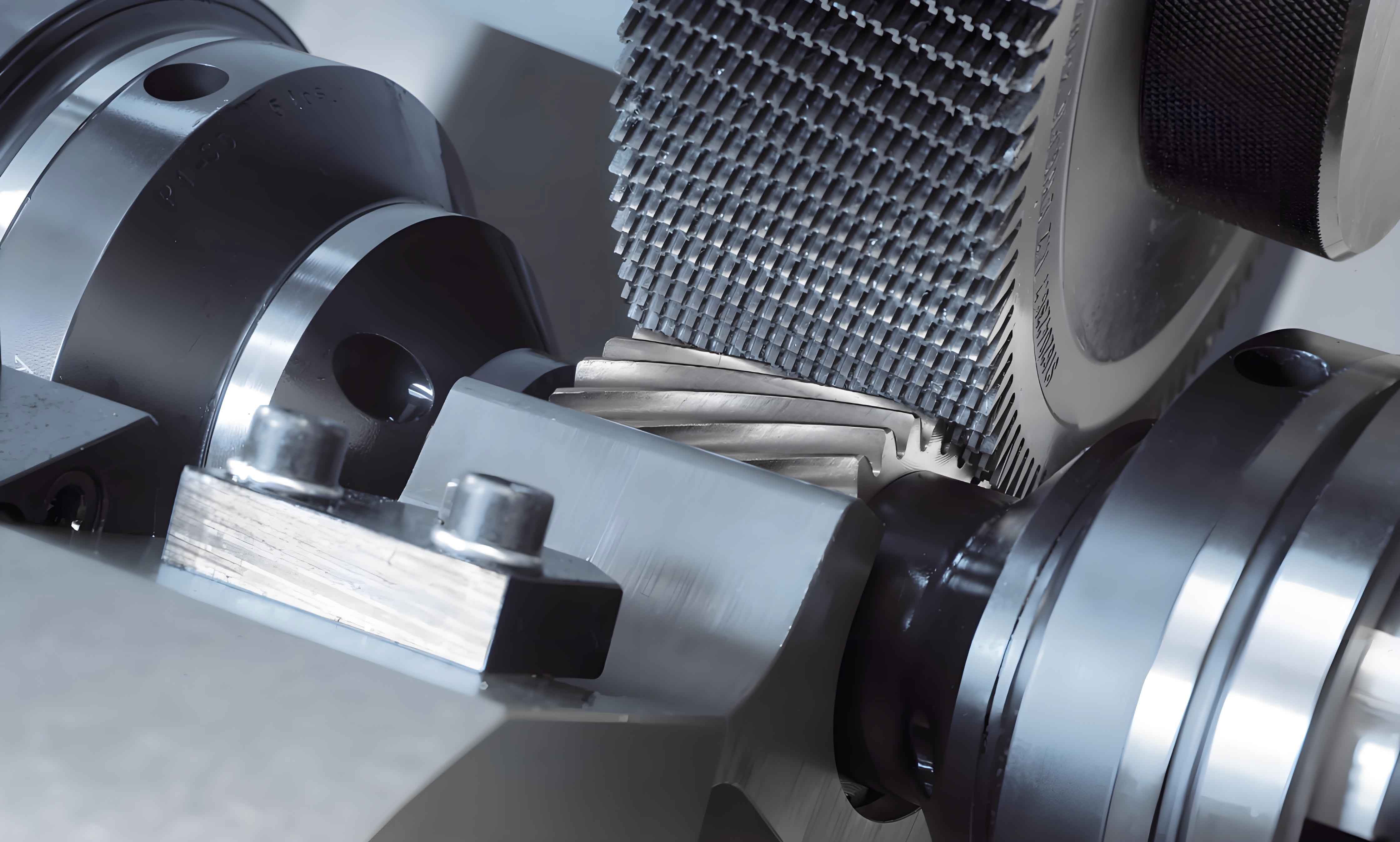
The core objective of this project was to eliminate this thermal dependency and achieve a stable, predictable gear shaving process. The proposed solution centers on the direct, real-time measurement and compensation of the shaving tool spindle to workpiece spindle center distance. This is achieved by installing a high-precision displacement sensor, termed here as the ΔZ-axis sensor, to physically probe a fixed reference plane on the machine structure relative to the tool spindle assembly. Any thermal growth that changes the effective center distance is detected as a change in this sensor reading. This measured deviation is then fed back to the machine’s CNC system, which automatically applies a compensating offset to the Z-axis (typically the axis controlling the workpiece spindle position) to nullify the error before the next gear shaving cycle begins. This creates a closed-loop control system for the most critical parameter in gear shaving.
System Design and Implementation
The successful implementation of this sensor-based compensation system required meticulous attention to mechanical design, sensor integration, and metrology principles. The system comprises several key components that must work in concert to achieve micron-level stability.
1. Displacement Sensor Selection and Integration
The choice of displacement sensor was paramount. The sensor must offer sub-micron resolution and repeatability to detect the minute changes in center distance that correlate to normal chord variations on the order of a few microns. Furthermore, seamless integration with the existing machine CNC was non-negotiable. The sensor output signal (e.g., analog voltage ±10V, digital SSI, or Profinet) must be directly readable by the CNC controller. The CNC must then be capable of executing a macro program that reads this sensor value, compares it to a pre-set master “zero” reference value (established at a known machine temperature and center distance), calculates the required Z-axis offset, and applies it dynamically. The selection criteria are summarized below:
| Parameter | Requirement | Rationale |
|---|---|---|
| Measurement Range | ±0.1 mm to ±0.5 mm | Must cover maximum expected thermal drift. |
| Resolution | < 0.1 µm | Necessary to control normal chord within 0.03 mm tolerance. |
| Repeatability | < ±0.2 µm | Critical for consistent, reliable compensation. |
| Output Signal | Compatible with host CNC (e.g., analog, SSI) | Enables direct data transfer for real-time compensation. |
| Environmental Rating | IP67 minimum | To withstand coolants, oils, and metal chips in the shop floor environment. |
| Probe Type | Hardened, wear-resistant tip (e.g., ruby) | For longevity and measurement stability against frequent contact. |
2. Mechanical Design for Metrological Integrity
The sensor itself is only as good as its mounting. The goal was to create an unbroken chain of precision from the machine’s foundational structure to the sensor’s probe tip. The design involved three custom components: a Fixed Mounting Bracket attached to the machine bed, a Precision Spacer Block, and a Sensor Mounting Plate.
Fixed Mounting Bracket: This component is permanently and rigidly attached to a stable, temperature-cycled location on the machine bed, ideally near the workpiece spindle base. Its mounting surface is meticulously scraped to ensure a high-degree of flatness and coplanarity with the machine’s inherent reference planes.
Precision Spacer Block: This block acts as the critical length standard. It is machined from high-grade, thermally stable material (e.g., stainless steel or granite) and subjected to stress relieving and aging treatments to minimize internal stress and long-term dimensional change. Its parallel faces are ground and lapped to extreme tolerances for flatness and parallelism. A unique feature is the incorporation of a master locating keyway, which mates with a corresponding key on the Sensor Mounting Plate. This keyed connection ensures precise rotational alignment, eliminating any potential angular error during assembly or maintenance. The required specifications are severe:
- Flatness of each mounting face: ≤ 0.003 mm
- Parallelism between faces: ≤ 0.005 mm
- Surface Roughness (Ra): ≤ 0.4 µm
Sensor Mounting Plate: This plate interfaces directly with the displacement sensor. It features a precision-bored pilot diameter to locate the sensor body and a finely finished front face to ensure the sensor’s measuring axis is perpendicular to the reference plane. The keyway is machined in a matched operation with the Precision Spacer Block’s key to guarantee a perfect fit. Tolerances are similarly strict.
The assembly sequence establishes the reference length. The Precision Spacer Block is bolted to the Fixed Mounting Bracket. The Sensor Mounting Plate is then located via the master key and bolted to the Spacer Block. Finally, the displacement sensor is inserted into the pilot bore of the Mounting Plate and secured. This creates a rigid, kinematically defined structure whose “length” from the machine bed to the sensor’s mounting face is fixed and known with high precision.
3. Reference Target Surface Preparation
The displacement sensor’s probe contacts a reference target surface on the movable component of the tool spindle housing or a rigid element directly connected to it. This surface must be prepared to the highest metrological standards. It is scraped to achieve exceptional flatness (target ≤ 0.005 mm over the contact area) and a fine surface finish. Most critically, this surface must be wear-resistant. As the probe touches this surface before every machining cycle (or at defined intervals), any wear would introduce a systematic error into the compensation loop, leading to a gradual drift in gear shaving dimensions. Regular verification of this surface’s condition is essential for preventative maintenance.
4. Compensation Logic and CNC Workflow
The compensation system operates on a simple but powerful principle. A master reference sensor value (\(S_{ref}\)) is captured when the machine is at a standardized thermal state (e.g., after warm-up cycle) and the center distance is known to be correct, producing a good part. This value is stored in the CNC.
Before each gear shaving cycle (or after a set number of cycles), the CNC executes a macro that commands the machine to move the tool spindle to the sensor measurement position. The displacement sensor reads the current value (\(S_{curr}\)). The deviation (\(\Delta S\)) is calculated:
$$\Delta S = S_{curr} – S_{ref}$$
This deviation \(\Delta S\) corresponds directly to the change in the effective center distance (\(\Delta A_c\)) due to thermal expansion/contraction. The CNC then calculates the required compensation offset for the Z-axis (\(\Delta Z_{comp}\)). The relationship is a machine-specific gain factor (k), often close to 1, determined through empirical testing:
$$\Delta Z_{comp} = k \cdot \Delta S$$
This \(\Delta Z_{comp}\) value is applied to the workpiece Z-axis position for the subsequent gear shaving operation, effectively canceling out the thermally induced error. The theoretical center distance (\(A_{c\_theoretical}\)) is thus maintained as the effective center distance (\(A_{c\_effective}\)):
$$A_{c\_effective} = A_{c\_theoretical} – \Delta Z_{comp} \approx A_{c\_theoretical}$$
The workflow can be summarized in the following logic sequence, executed automatically by the CNC:
- Pause production cycle.
- Move shaving tool spindle to sensor measurement position.
- Trigger displacement sensor and read \(S_{curr}\) into CNC variable.
- Compute deviation: \(\Delta S = S_{curr} – S_{ref}\).
- If \(|\Delta S| >\) tolerance (e.g., 0.002 mm), proceed; else, skip compensation.
- Compute Z-axis compensation offset: \(\Delta Z_{comp} = k \cdot \Delta S\).
- Apply \(\Delta Z_{comp}\) as a fixture offset or direct axis shift to the workpiece Z-axis.
- Retract spindle from sensor.
- Proceed with normal gear shaving cycle on next workpiece.
Results, Data Analysis, and Validation
The implementation of the ΔZ-axis displacement sensor system was tested on a production gear shaving cell. The test involved machining a batch of helical gears for a transmission shaft (part family similar to described). The normal chord specification was 34.000 mm with a tolerance of ±0.015 mm (total tolerance 0.030 mm). The process was allowed to reach thermal equilibrium and then run over an extended period simulating a production shift, including periods of idle time to induce thermal cycling.
Data was collected using periodic in-process gauging. The normal chord values for a sample of 125 consecutive parts, grouped into 25 subgroups of 5, were recorded. The results were subjected to a comprehensive process capability analysis. A snapshot of the recorded data is presented below:
| Subgroup | X1 (mm) | X2 (mm) | X3 (mm) | X4 (mm) | X5 (mm) |
|---|---|---|---|---|---|
| 1 | 34.023 | 34.011 | 34.017 | 34.014 | 34.019 |
| 2 | 34.017 | 34.013 | 34.017 | 34.017 | 34.018 |
| 3 | 34.016 | 34.013 | 34.014 | 34.022 | 34.015 |
| … | … | … | … | … | … |
| 24 | 34.018 | 34.020 | 34.017 | 34.015 | 34.020 |
| 25 | 34.016 | 34.024 | 34.017 | 34.010 | 34.010 |
The statistical analysis yielded the following key process metrics, calculated using standard formulas:
Overall Standard Deviation (Standard Deviation Overall): $$\sigma_{overall} = 0.00360 \text{ mm}$$
Within-Subgroup Standard Deviation (Standard Deviation Within): $$\sigma_{within} = 0.00348 \text{ mm}$$
Process Mean: $$\bar{X} = 34.0154 \text{ mm}$$
Specification Limits: $$LSL = 34.000 \text{ mm}, \quad USL = 34.030 \text{ mm}$$
The process capability indices were calculated as follows, demonstrating the dramatic improvement:
$$C_p = \frac{USL – LSL}{6\sigma_{within}} = \frac{0.030}{6 \times 0.00348} \approx 1.44$$
$$C_{pk} = \min\left( \frac{\bar{X} – LSL}{3\sigma_{within}}, \frac{USL – \bar{X}}{3\sigma_{within}} \right) = \min\left( \frac{0.0154}{0.01044}, \frac{0.0146}{0.01044} \right) = \min(1.47, 1.40) = 1.40$$
The long-term performance indices (Pp, Ppk) were also above 1.33. The analysis software generated a process control chart (not reproduced here in data but described) showing all points within control limits and no discernible non-random trends, indicating a stable process. The calculated Cpk of 1.40 significantly exceeds the target of 1.33 and is a marked improvement over the baseline capability of approximately 1.1 achieved with the manual compensation method.
Conclusion and Industrial Impact
The integration of a high-precision displacement sensor for real-time thermal compensation in gear shaving has proven to be a highly effective and robust solution to a long-standing manufacturing challenge. By directly addressing the root cause of variation—thermal deformation altering the tool-workpiece center distance—this closed-loop system transforms gear shaving from a skill-dependent, manually adjusted process into a stable, automated, and predictable one.
The key outcomes and benefits of this implementation are substantial:
- Achievement of High CPK: The process consistently delivers a Cpk > 1.33, meeting and exceeding automotive and high-precision industry standards, thereby validating the process for statistical control and enabling the rationalization of inspection routines.
- Elimination of 100% Inspection: The reliable process capability allows for a shift from 100% inspection of the normal chord to reduced frequency SPC-based sampling. This directly reduces labor costs, inspection bottlenecks, and handling damage.
- Enhanced Automation Compatibility: The self-correcting nature of the machine removes the need for operator intervention for size adjustments. This is a critical enabler for integrating the gear shaving machine into automated production lines, unmanned shifts, and Industry 4.0 smart factory environments.
- Reduced Variability and Scrap: The proactive compensation prevents out-of-specification parts from being generated, reducing scrap and rework costs associated with thermal drift.
- Lower Operational Skill Dependency: The process becomes more robust and less dependent on the experience and constant attention of a skilled operator, simplifying training and staffing.
In conclusion, this sensor-based compensation methodology represents a significant advancement in gear shaving technology. It aligns perfectly with the modern mandates of high precision, low waste, and automated manufacturing. The principles demonstrated—direct measurement of critical process variables and real-time CNC-integrated feedback—are applicable beyond this specific case, offering a blueprint for enhancing stability and capability in other precision machining processes where thermal effects are a dominant source of variation. The successful application in gear shaving provides a compelling case study for the tangible benefits of integrating metrology directly into the machining control loop.