
In my years of experience maintaining industrial equipment, I have encountered numerous issues with worm gear reducers. These components are critical in low-speed, high-torque applications, and their failure can lead to significant production losses and safety hazards. In this article, I will share my insights on the common faults of worm gear reducers, their causes, and effective solutions, based on my work with RV series worm gear reducers. The worm gear is a key element in many transmission systems, and understanding its failure modes is essential for reliable operation.
The worm gear reducer is a power transmission device that uses a worm (screw) and a worm gear (wheel) to achieve a large reduction ratio. The worm gear typically has a lower material hardness than the worm, which leads to inevitable wear over time. The RV series worm gear reducer, with its compact aluminum alloy housing and high efficiency, is widely used in industries such as chemical processing, packaging, and material handling. Below is an illustration of a typical RV series worm gear reducer structure.
1. Overview of Worm Gear Reducers
1.1 Device Characteristics
The worm gear reducer is designed to convert high-speed input from an electric motor into low-speed, high-torque output. Its key characteristics include a large transmission ratio, smooth and quiet operation, and a compact structure. The worm gear is the most vulnerable component because it is subjected to continuous sliding friction against the harder worm. In my practice, I have observed that the worm gear often wears out before any other part, leading to reduced efficiency and eventual failure.
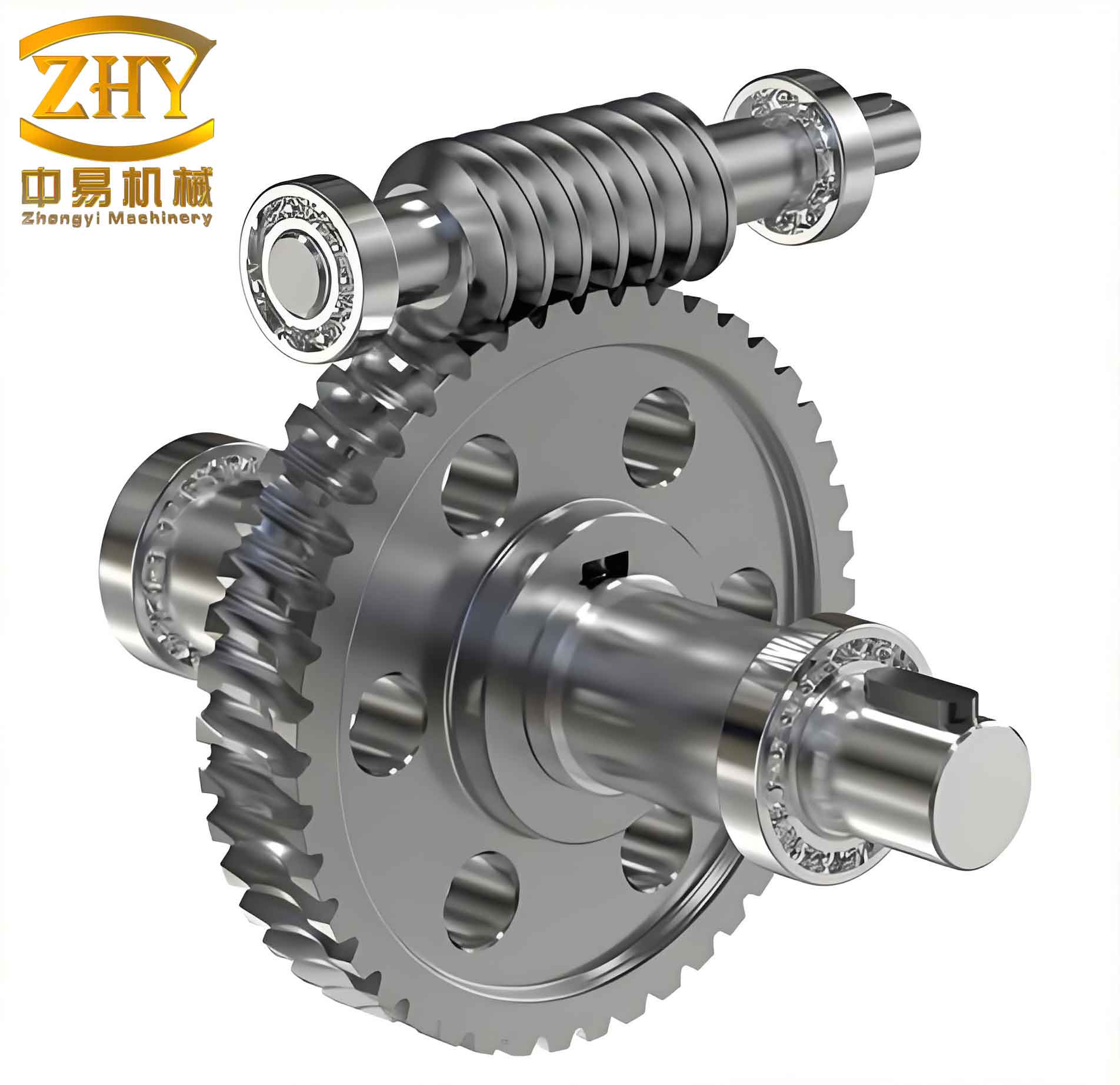
1.2 Mechanical Structure of RV Series
The RV series worm gear reducer consists of several key components: the worm, oil seal, flange, bearings, housing, retaining ring, oil seal cover, worm gear, and oil plug. The housing is made of die-cast aluminum alloy (ZL401) for lightweight and good heat dissipation. The oil seal, typically made of nitrile rubber or fluororubber, prevents lubricant leakage. The worm is supported by roller bearings, and the worm gear is mounted on a shaft with appropriate support. The entire assembly is designed to minimize backlash and maximize efficiency.
1.3 Types of Worm Drives
There are three main types of worm drives: cylindrical worm drives, enveloping worm drives, and cone worm drives. Each has distinct characteristics suitable for different applications.
| Type | Key Features | Applications |
|---|---|---|
| Cylindrical worm (Archimedes, Involute, etc.) | Simple geometry, easy to manufacture; Archimedes worm has straight line profile in axial section; Involute worm has involute profile in transverse plane. | General power transmission, medium speeds |
| Enveloping (Globoid) worm | Multiple teeth in contact, higher load capacity, better lubrication film formation, higher efficiency. | Heavy duty, high load applications |
| Cone worm | High contact ratio, large reduction ratio (10–400), favorable lubrication angle. | High-ratio drives, aerospace |
The most commonly used in RV series reducers are cylindrical worm gears, particularly the ZI (involute) type for its smooth meshing and high load capacity.
1.4 Materials for Worm and Worm Gear
Material selection is critical for the performance and life of a worm gear pair. The worm gear must have good wear resistance and anti-scoring properties, while the worm requires sufficient strength and hardness. Typical materials are listed below.
| Component | Material | Properties | Application |
|---|---|---|---|
| Worm Gear | Tin bronze (ZCuSn10P1, ZCuSn5Pb5Zn5) | Excellent wear resistance, good anti-scoring, high cost, moderate strength. | Sliding speed > 3 m/s |
| Aluminum-iron bronze (ZCuAl10Fe3) | Lower wear resistance, anti-scoring moderate, lower cost, higher strength. | Sliding speed < 4 m/s | |
| Gray cast iron | Low efficiency, low cost. | Sliding speed < 2 m/s | |
| Worm | 40/45 steel (quenched and tempered) | Hardness 220–300 HBS | Low-speed drives |
| 40/45 steel (surface hardened) | Hardness 45–55 HRC | General drives | |
| 20CrMnTi, 20Cr (carburized) | Hardness 56–62 HRC | High-speed, heavy-load drives |
In recent years, zinc-aluminum alloy (ZA27) has emerged as a cost-effective alternative to tin bronze for worm gear applications, offering comparable wear resistance and 3–5 times longer life at 25–30% lower cost.
1.5 Applications
Worm gear reducers are used in a wide range of industries: rolling mills in metallurgy, anchor winches on ships, chemical stirrers, packaging lines, overhead cranes, and building maintenance platforms. Their ability to provide high torque at low speed in a compact package makes them indispensable.
2. Common Fault Types and Their Solutions
Based on my field experience, I have identified five major categories of failures in worm gear reducers: overheating, oil leakage, vibration, worm gear wear, and abnormal noise. Each fault has specific causes and remedies, which I will detail below with supporting mathematical analysis where applicable.
2.1 Overheating
Excessive temperature rise in a worm gear reducer can accelerate lubricant degradation, reduce material strength, and lead to seizure. The causes and solutions are summarized in the following table.
| Cause | Solution |
|---|---|
| Improper alignment between reducer and driven machine | Realign components to ensure coaxiality |
| Overload condition | Reduce load or increase reducer size |
| Excessive friction at oil seal | Apply a few drops of lubricant to seal lip |
| Insufficient or excessive lubricant level | Adjust oil level to manufacturer’s specification |
| Contaminated or degraded lubricant | Drain and replace with recommended oil |
The heat generation in a worm gear reducer is primarily due to sliding friction. The power loss can be expressed as:
$$P_{\text{loss}} = P_{\text{in}} (1 – \eta)$$
where \(P_{\text{in}}\) is the input power and \(\eta\) is the mechanical efficiency. The efficiency of a worm gear drive depends on the lead angle \(\gamma\) and the equivalent friction angle \(\rho\):
$$\eta = \frac{\tan\gamma}{\tan(\gamma + \rho)}$$
For a typical self-locking worm gear, \(\gamma\) is small, so efficiency is low and heat generation is high. The heat dissipation must balance the heat generation to maintain a stable temperature. The heat balance equation is:
$$P_{\text{loss}} = h A (T – T_{\text{amb}})$$
where \(h\) is the heat transfer coefficient, \(A\) is the surface area, \(T\) is the oil temperature, and \(T_{\text{amb}}\) is ambient temperature. In my experience, if the oil temperature exceeds 80°C, immediate action is required to prevent damage to the worm gear.
2.2 Oil Leakage
Oil leakage not only wastes lubricant but also poses safety risks. Common causes and remedies are listed below.
| Cause | Solution |
|---|---|
| Worn oil seal lip | Replace oil seal |
| Scored or worn shaft surface at seal contact area | Replace shaft or use a wear sleeve; in severe cases, replace worm gear assembly |
| Drain plug not tightened | Apply thread sealant and tighten plug |
| Damaged oil level indicator (sight glass) | Replace the indicator |
I always recommend using high-quality double-lip oil seals made of fluororubber (FKM) for high-temperature applications, as they offer better resistance to wear and chemical attack.
2.3 Vibration
Excessive vibration can lead to bearing failure, increased wear, and even catastrophic failure. Vibration sources in worm gear reducers are often related to misalignment, wear, or loosening of components.
| Cause | Solution |
|---|---|
| Insecure mounting of reducer or driven equipment | Reinforce foundation and re-tighten bolts |
| Worn or damaged worm gear teeth | Replace worm and worm gear as a set |
| Bearing wear or damage | Replace bearings with appropriate type (e.g., tapered roller bearings for axial loads) |
| Loose bolts on housing or flanges | Torque all bolts to specification |
Vibration analysis can be used to diagnose wear. The fundamental frequency of the worm gear mesh is calculated as:
$$f_m = \frac{n_1 Z_1}{60}$$
where \(n_1\) is worm speed in RPM and \(Z_1\) is the number of starts on the worm. An increase in vibration amplitude at this frequency often indicates tooth wear or pitting.
2.4 Worm Gear Wear
Wear of the worm gear teeth is the most common failure mode. Because the worm gear is made of softer material than the worm, it suffers from abrasive and adhesive wear. The factors influencing wear rate are shown in the following table.
| Cause | Solution |
|---|---|
| Overload beyond design capacity | Reduce operating load or upgrade reducer size |
| Incorrect lubricant grade or viscosity | Use recommended lubricant (e.g., synthetic PAO with EP additives) |
| Insufficient lubricant quantity | Maintain oil level at center of sight glass |
| Prolonged operation without oil change | Follow scheduled oil changes (typically every 2000–3000 hours or 6 months) |
| High operating temperature accelerating oil degradation | Improve cooling or use oil with higher thermal stability |
The wear volume can be estimated using Archard’s wear equation:
$$V = k \frac{F s}{H}$$
where \(V\) is the wear volume, \(k\) is the wear coefficient, \(F\) is the normal load, \(s\) is the sliding distance, and \(H\) is the hardness of the softer material. For worm gear drives, the sliding velocity is high, so the sliding distance \(s\) accumulates rapidly. I have found that using zinc-aluminum alloy for the gear can reduce \(k\) significantly compared to aluminum bronze, extending service life.
2.5 Abnormal Noise
Unusual sounds from a worm gear reducer indicate meshing problems, bearing issues, or lubrication deficiencies. The table below lists typical causes and corrective actions.
| Cause | Solution |
|---|---|
| Misalignment between reducer and motor/load | Re-align using dial indicator |
| Worn or damaged bearings | Replace bearings; check for proper preload |
| Poor tooth contact or pitting on worm gear | Adjust axial position of worm or replace worn gear set |
| Insufficient lubrication (starving) | Top up lubricant; check oil passages |
I often use a stethoscope or vibration analyzer to pinpoint the noise source. For example, a rhythmic clicking sound every revolution of the worm gear often indicates a broken tooth or severe pitting.
3. Maintenance and Care Practices
Proper maintenance is essential to maximize the lifespan of a worm gear reducer. Based on my hands-on experience, I recommend the following best practices:
- Operating ambient temperature should be between -10°C and +40°C. If extreme temperatures are unavoidable, use specially formulated lubricants.
- If the reducer has been stored or idle for 4–6 months, replace the oil seals before restarting, as rubber may become brittle or adhere to the shaft.
- Check the oil level regularly using the sight glass. Maintain oil at the center of the indicator.
- Use only recommended lubricants. For RV series worm gear reducers, I prefer ISO VG 320 or 460 synthetic gear oils with EP additives.
- Change the oil every 2000–3000 operating hours or every 6 months, whichever comes first. Flush the housing with flushing oil before adding new oil.
- Inspect the worm gear tooth profile during every oil change. If more than 30% of the tooth thickness has worn away, replace the gear set.
- Monitor bearing temperatures. If bearing temperature exceeds 90°C, investigate immediately.
The relationship between lubricant viscosity and temperature can be approximated by the Walther equation:
$$\log \log (\nu + 0.7) = A – B \log T$$
where \(\nu\) is kinematic viscosity in cSt, \(T\) is absolute temperature in K, and \(A, B\) are constants. Using this, I can determine the correct oil viscosity at operating temperature to ensure adequate film thickness.
Another critical parameter is the thermal rating of the reducer. The thermal power limit \(P_{\text{th}}\) is given by:
$$P_{\text{th}} = \frac{h A (T_{\text{max}} – T_{\text{amb}})}{1 – \eta}$$
If the applied load exceeds this thermal rating, the reducer will overheat unless additional cooling is provided (e.g., fan cooling or oil cooler).
In summary, worm gear reducers are robust but require careful monitoring and timely maintenance. By understanding the common failure modes—overheating, oil leakage, vibration, wear, and noise—I have been able to extend the life of many worm gear drives in my facility. Regular inspection of the worm gear condition, proper lubrication, and alignment checks are the keys to avoiding unscheduled downtime. The worm gear remains the most critical component, and its material selection and maintenance directly impact the overall reliability of the reducer.
I hope this comprehensive overview helps fellow engineers and technicians better diagnose and solve worm gear reducer problems. With proper care, a worm gear reducer can provide many years of reliable service.