
Using the method of numerical comparison, the simulation results are accurately analyzed by calculating the normal difference between VERICUT gear shaping simulation tooth surface and theoretical tooth surface.
1. Tooth surface measurement grid planning
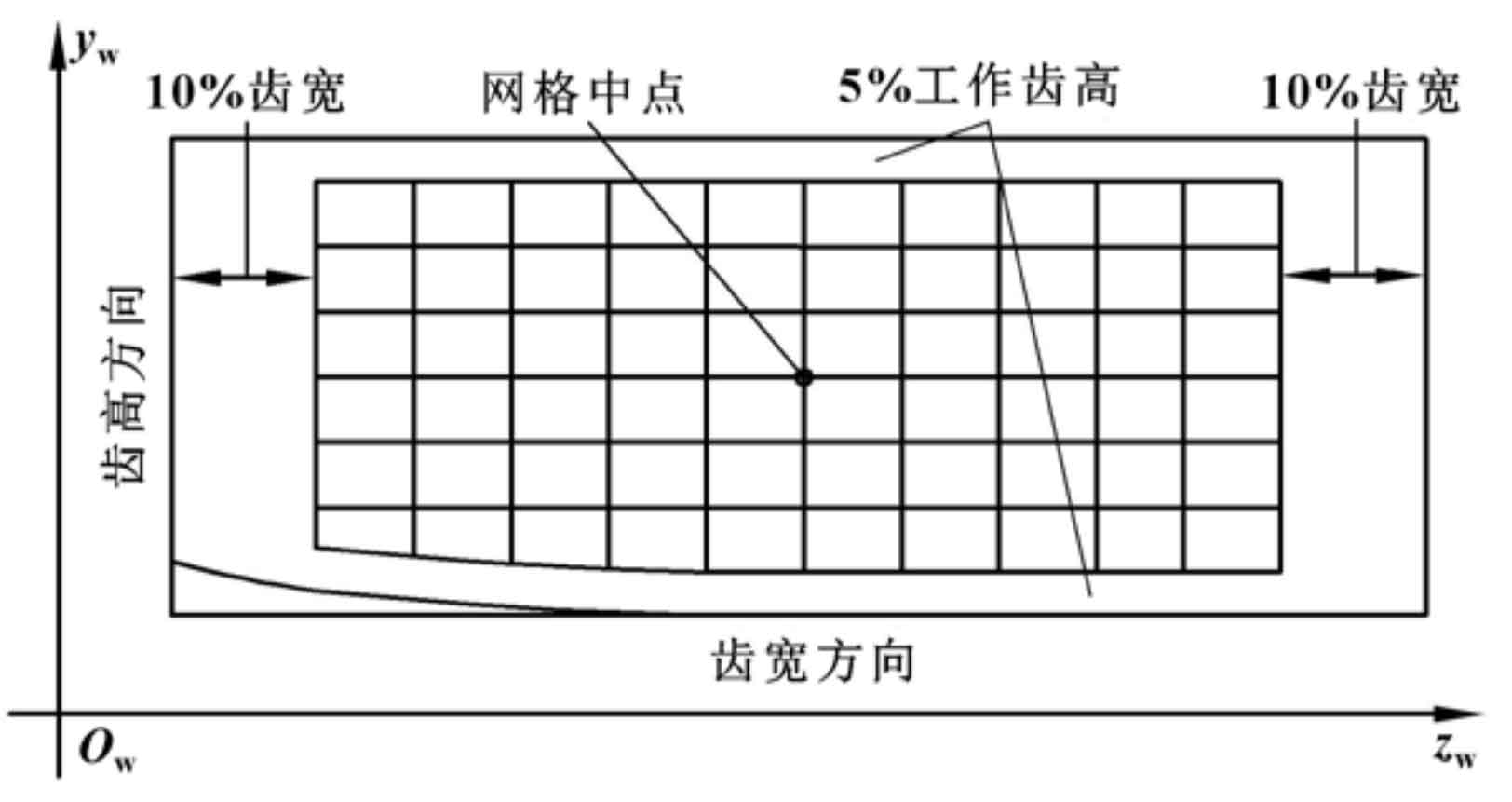
In order to accurately calculate the deviation between the simulated tooth surface and the theoretical tooth surface, the face gear tooth surface is discretized. Because the two tooth surfaces of helical offset non orthogonal gear are asymmetric, it is necessary to discretize the two tooth surfaces respectively. In the coordinate system SW, the mesh is divided on the rotating projection surface of the working tooth surface of the face gear. The measuring area of tooth surface shall not be too close to the transition surface of tooth top, tooth root and large and small end faces. As shown in Figure 1, take 7 rows in the direction of tooth height and 11 rows in the direction of tooth width, with a total of 77 measuring points. The measured mesh tooth height boundary shrinkage is 5% of the working tooth height, and the tooth width boundary shrinkage is 10% of the actual tooth width.
2. Calculation of tooth surface deviation
By discretizing the theoretical gear tooth surface, the coordinates RM (I, J) of each grid point on the tooth surface and the corresponding unit normal vector nm (I, J) can be obtained, where I = 1 ~ 7 and j = 1 ~ 11; Then take the discrete theoretical surface as the gear tooth surface (7 × 11 grid tooth surface) as the measurement reference, in Section 3 On the STL model saved in Section 4, extract the coordinate value RV (I, J) of the point corresponding to the theoretical tooth surface grid point; Through the formula, the normal deviation between the simulated tooth surface and the theoretical tooth surface of face gear can be calculated. The calculation results of tooth surface deviation are shown in Figure 2.
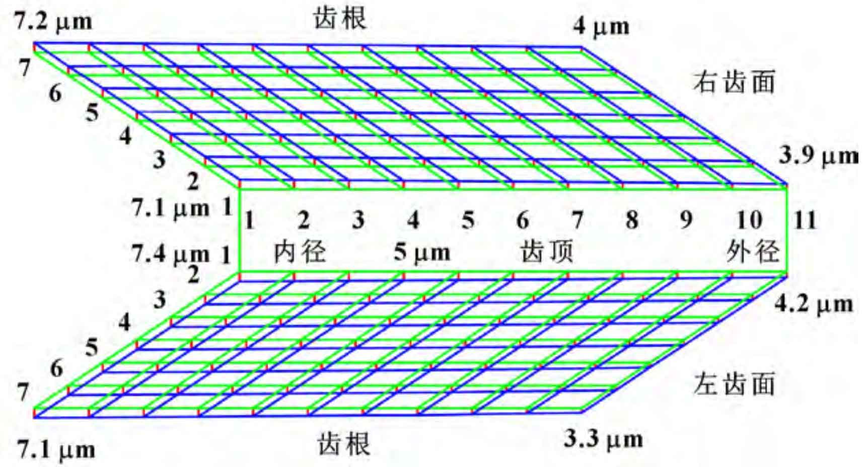
Compared with the theoretical tooth surface, the simulation deviation of helical offset non orthogonal gear shaping is the residual of the tooth surface, and the maximum residual of the left tooth surface is 7 four μ m. The minimum residue is 3 three μ m. The maximum residue on the right tooth surface is 7.5% two μ m. The minimum residue is 3 nine μ m。 The error may be caused by two aspects: on the one hand, it is caused by the model conversion of VERICUT software and the tolerance of NC interpolation; On the other hand, it is caused by the envelope residual of gear shaper machining. Even if there is deviation in the simulation results, according to the national standard evaluation of bevel gear accuracy, the tooth profile accuracy of face gear meets the requirements of grade 5.