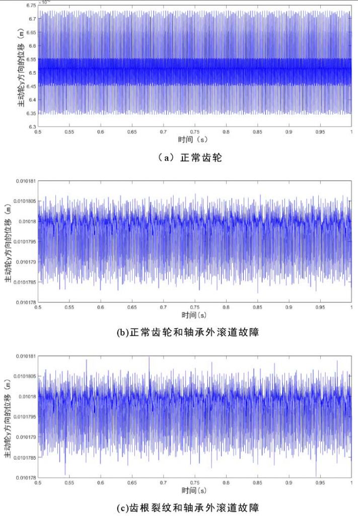
As shown in figure (a) is the time domain diagram of the displacement and vibration analog signal of the driving wheel in the 𝑦 direction when the gear has no fault and the supporting rolling bearing has no fault. It can be seen from the figure that the gear is running in a stable state. Figure (b) shows the time domain diagram of the displacement and vibration analog signal of the driving wheel in the 𝑦 direction when the gear has no fault and the outer raceway of the supporting rolling bearing has a single fault. Compared with figure (a), the vibration signal of the gear in figure (b) begins to show a slight periodic impact component.

Figure (c) is the time domain diagram of displacement vibration analog signal in 𝑦 direction when there is a single fault in the outer raceway of bearing bearing with root crack fault. From the diagram, we can see that there is a very obvious impact signal, which is caused by system fault, but it is not sure which kind of fault is caused by the impact signal.
Through the comparison of these three pictures, we can find that the time domain diagram can be used to judge whether there is fault signal in the gear rolling bearing system, but it can not be determined by the time-domain analysis what fault is caused by. Therefore, the type of fault and which component the fault is located in can not be analyzed by using the time domain parameters. In the following research, the vibration signal of the system is mainly studied Line spectrum analysis.
