
In my work on heavy machinery drives, I have repeatedly seen that the quality of a gear begins with the quality of its blank. A gear transmits motion and power, changes speed and torque, and carries alternating contact and bending loads during every revolution. The teeth experience contact pressure, sliding friction, root bending stress, and sometimes impact when meshing is imperfect. These conditions lead to pitting, wear, and tooth fracture. For large gears, the blank route therefore becomes a strategic decision: it must satisfy mechanical duty, inspection acceptance, manufacturing feasibility, delivery, and cost. My design approach for large forged gear blanks in this class is to separate the highly stressed tooth ring from the less stressed hub, use a forged ring for the teeth, use a cast hub for the support structure, and join the two into one composite gear blank before gear cutting. This approach preserves the quality of forged gear blanks where it matters most while avoiding the cost and capacity limits of forging an entire large gear body.
The gear in my case study was a large driven gear in a converter tilt reducer. It operated at low speed under heavy load and shock. The original design was a single cast blank. The casting route offered shape freedom and low machining allowance, but the tooth-root region after hobbing often fell near the center of the rim, where casting defects are difficult to eliminate. The acceptance requirement for ultrasonic testing was severe, and the achievable yield was low. I therefore evaluated a composite structure in which the ring was made from forged gear blanks and the hub remained a casting. The final blank was welded and pinned into one body, then machined and cut. The result met the quality target and reduced manufacturing risk. The following sections document the reasoning, calculations, process parameters, inspection logic, and production controls that I used.
Functional duty and stress basis. I began by restating the duty of the gear rather than starting from the manufacturing route. The gear is a low-speed, high-torque member. Its tooth flanks see repeated Hertzian contact stress, and its tooth roots see alternating bending stress. Because the load is not perfectly uniform, I included application, dynamic, face-load, and transverse-load factors in the rating checks. The contact stress can be represented in the conventional form as
$$ \sigma_H = Z_E Z_H Z_\varepsilon \sqrt{\frac{F_t}{b d_1}\frac{u+1}{u}K_A K_V K_{H\beta}K_{H\alpha}} $$
and the root bending stress as
$$ \sigma_F = \frac{F_t}{b m_n}Y_F Y_S Y_\beta K_A K_V K_{F\beta}K_{F\alpha} \le \sigma_{FP} $$
where \(F_t\) is the nominal tangential load, \(b\) is the face width, \(d_1\) is the reference diameter, \(u\) is the gear ratio, \(m_n\) is the normal module, and the \(K\) terms represent application, dynamic, face-load, and transverse-load effects. The allowable contact and bending stresses are not the only criteria. For a large blank, the subsurface quality beneath the tooth root is equally important. If a casting defect lies in the root region, the local stress concentration can dominate fatigue life even when the nominal stress is acceptable. This was the central reason for changing the tooth ring to forged gear blanks and keeping the casting in the hub.
| Failure mode | Dominant stress or mechanism | Blank quality requirement | Composite design response |
|---|---|---|---|
| Tooth flank pitting | Repeated Hertzian contact stress | Sound material under the flank, controlled hardness, clean steel | Forged ring with adequate forging ratio and ultrasonic testing |
| Tooth flank wear | Sliding friction and surface pressure | Uniform hardness and microstructure | Quenched and tempered ring at 250 to 280 HBW before cutting |
| Tooth root fatigue | Alternating bending stress and stress concentration | No harmful defects in the root region | Forged gear blanks for the ring, with the weld and pins kept away from the root zone |
| Tooth fracture under shock | Impact and overload | High toughness and sound core | Forged 35CrMo ring and cast ZG35CrMo hub with controlled weld procedure |
| Hub cracking or distortion | Bending and thermal stress in service | Adequate section and inspection level | Cast hub with lower but controlled ultrasonic acceptance and stress relief after welding |
Conventional routes and their limits. The common blank routes for gears are forging and casting. For small and medium gears, I prefer forged gear blanks because forging closes internal porosity, refines grain structure, and produces a continuous grain flow that follows the tooth profile after machining. For very large gears, however, forging the entire body is limited by press capacity, ring-rolling capacity, handling, and cost. Above roughly 2 m in diameter, a solid forged body often becomes impractical. Casting then becomes attractive because the external shape can be produced close to final size, the machining allowance is small, and the piece cost is lower. The weak point is internal quality. Cast steel gears can be sound, but the combination of a large section, a special rim shape, and a tooth root that sits near the mid-thickness of the rim makes inspection and defect removal difficult. A casting yield of about 60% was not unusual in the original route, and the rejection risk increased when class I ultrasonic acceptance was required.
| Comparison item | Cast gear blank | Forged gear blank | Composite cast-forged blank used in my design |
|---|---|---|---|
| Shape freedom | High | Low to moderate | HighOverall, because only the ring is forged |
| Internal soundness | Process-sensitive | High when forging ratio is sufficient | High in the tooth ring and controlled in the hub |
| Grain flow | Isotropic but less directional | Favorable around the ring | Favorable in forged gear blanks and acceptable in the cast hub |
| Inspection risk | High near the tooth root | Lower in the ring | Ultrasonic testing concentrated on the forged ring and weld zone |
| Machining allowance | Low | Moderate | Moderate, with allowance controlled on the ring and hub interfaces |
| Tooling and capacity | Pattern and foundry capacity | Press or ring-rolling capacity | Ring rolling for the ring and foundry for the hub |
| Cost driver | Foundry yield and repair rate | Forging size and machining | Only the highly stressed ring uses forged gear blanks |
| Best application | Large, complex, lower-stress bodies | Highly stressed teeth and smaller gears | Large gears where tooth quality and body cost must be balanced |
Case background and design decision. The gear in question was a large driven gear in a converter tilt reducer, with a diameter above 3 m. The original blank was cast in ZG40Mn2 and was required to meet ultrasonic class I of the applicable cast-steel nondestructive testing standard. In practice, the combination of the large rim, the tooth-root location, and the class I requirement made the casting route very difficult. The number of foundries that could quote the part was limited, and the risk of rejection after rough machining was high. I reviewed the load path and confirmed that the tooth ring was the critical region. The hub carried torque and provided mounting stiffness, but its stress state was less severe and its failure consequences were more tolerant of a lower inspection class. I therefore proposed a composite blank: a forged ring in 35CrMo, a cast hub in ZG35CrMo, a pinned and welded interface, and final machining after joining. This allowed forged gear blanks to be used only where the tooth root and flank required superior soundness, while the hub retained the shape and cost advantages of casting.
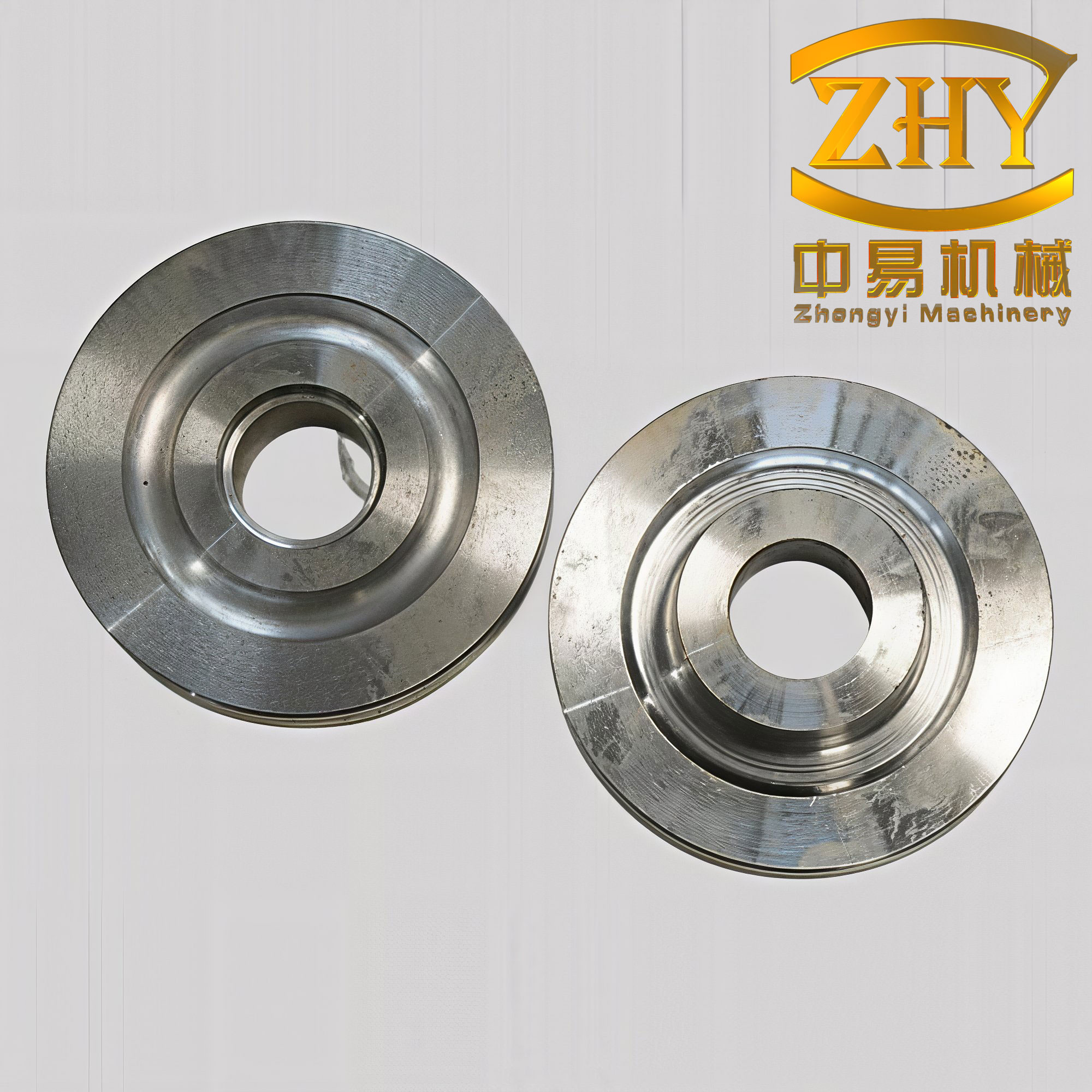
Composite architecture. The gear blank was divided into a ring, a hub, and a joining system. The ring carried the teeth and therefore used forged gear blanks. The hub was a casting with the mounting bore, web, and stiffening sections. The interface was arranged so that the weld was away from the final tooth root and so that the pins could transfer shear without creating a hard zone under the teeth. I used two rows of cylindrical pins, eight per side, positioned by marking after the mating surfaces were machined. The pins were not allowed to fall in the tooth-root region after hobbing. The ring and hub were then welded around the circumference. The weld closed the joint, provided sealing and continuity, and contributed to load transfer, but I did not rely on the weld alone for torque transmission. The pins and the interference-free fitted interface carried the main shear, while the weld carried tension, bending continuity, and local load redistribution.
| Element | Material or feature | Primary function | Critical control |
|---|---|---|---|
| Tooth ring | Forged 35CrMo ring | Carries contact and bending load in the teeth | Forging ratio not less than 3, ultrasonic class II, hardness 250 to 280 HBW |
| Hub | Cast ZG35CrMo | Provides mounting bore, web stiffness, and torque path | Cast radius R17 to R25, draft 1:20, ultrasonic class III |
| Mating surface | Machined fit between ring and hub | Maintains concentricity and distributes shear | Rough allowance about 5 mm per side before final machining |
| Pins | Cylindrical pins, eight per side | Resists relative slip and shear at the interface | Located away from the final tooth root |
| Weld | U-groove, 30 mm by 8 degrees | Joins the ring and hub into a single blank | Preheat 250 to 300 degrees C, controlled heat input, slow cooling |
| Stress relief | Thermal treatment after welding | Reduces welding residual stress | 520 plus or minus 20 degrees C, hold 3 h, cool to 350 degrees C before air cooling |
Material selection and weldability. I selected ZG35CrMo for the hub and forged 35CrMo for the ring. The two materials are sufficiently compatible for welding, and both provide the hardenability needed for a quenched and tempered gear blank in this size class. The ring must be clean and sound because it carries the tooth load. The hub must be castable, machinable, and weldable. I checked the carbon equivalent before approving the weld procedure. A useful first-order expression is
$$ CE = C + \frac{Mn}{6} + \frac{Cr+Mo+V}{5} + \frac{Ni+Cu}{15} $$
The composition and hardness targets were set so that the preheat and interpass conditions could be controlled without producing a hard, crack-sensitive heat-affected zone. I also required the ring and hub to be quenched and tempered before joining. The final stress relief was deliberately kept below the tempering temperature of the ring so that the ring hardness would not be reduced. The heat-treatment condition can be expressed as
$$ T_{SR} = T_{temper} – (20 \text{ to } 40)^\circ C $$
This rule protected the mechanical properties of the forged gear blanks while still reducing welding residual stress. For the actual process, I used a stress-relief temperature of 520 plus or minus 20 degrees C, a holding time of 3 h, and cooling to 350 degrees C before air cooling.
| Item | Hub requirement | Ring requirement | Reason |
|---|---|---|---|
| Material | ZG35CrMo casting | Forged 35CrMo | Compatible welding and adequate hardenability |
| Primary quality concern | Shrinkage, porosity, and cast surface defects | Internal soundness and grain flow | The ring carries tooth loads while the hub carries support loads |
| Ultrasonic acceptance | Class III | Class II | Higher quality where the tooth root will be cut |
| Hardness before machining | 250 to 280 HBW | 250 to 280 HBW | Machinability and tooth strength balance |
| Forging ratio | Not applicable | Not less than 3 | Closes porosity and improves grain flow in forged gear blanks |
| Weld preparation | U-groove 30 mm by 8 degrees | U-groove 30 mm by 8 degrees | Access for sound fusion and controlled heat input |
Design checks for the joint. A composite blank is only as good as its interface. I treated the pin group, the fitted surface, and the weld as a combined load-transfer system. The pins were checked in shear using
$$ \tau_p = \frac{F_t}{n A_p} \le \tau_{p,allow} $$
where \(n\) is the number of active pins and \(A_p\) is the pin shear area. I also checked bearing pressure on the pin holes, because a pin that is strong in shear can still damage a soft hole. The weld was sized with a throat model,
$$ a = 0.707 t $$
and the heat input was controlled using
$$ Q = \eta \frac{U I}{v} $$
where \(U\) is arc voltage, \(I\) is current, \(v\) is travel speed, and \(\eta\) is thermal efficiency. The purpose of this calculation was not to maximize deposition but to keep the heat-affected zone within the preheat and stress-relief window. For a large circumference, excessive local heat input can cause angular distortion and nonuniform hardness. I therefore specified alternating welds on opposite sides, multiple welders working symmetrically where practical, and a moderate current of about 200 A with a voltage of 27 to 30 V.
The thermal expansion mismatch between the ring and hub was also considered. Even when both materials are similar, the cast and forged product forms can have slightly different elastic and thermal histories. A first-order check is
$$ \Delta D = \alpha D \Delta T $$
This check informed the fit, the preheat, and the sequence of welding. I did not use a tight interference fit that would create excessive residual stress before welding. Instead, I used a machined fit that allowed assembly and pinning, with the weld providing final continuity after controlled preheat. This sequence reduced the risk of cracking during cooling and improved dimensional stability before gear cutting.
| Design check | Model or criterion | Purpose | Process consequence |
|---|---|---|---|
| Pin shear | \(\tau_p = F_t/(n A_p) \le \tau_{p,allow}\) | Prevents relative slip and pin overload | Eight pins per side, located away from the tooth root |
| Pin bearing | Local bearing pressure check | Protects the cast hub and ring holes | Controlled hole fit and sufficient engagement length |
| Weld throat | \(a = 0.707 t\) | Provides adequate fusion without excess heat | U-groove 30 mm by 8 degrees |
| Heat input | \(Q = \eta U I / v\) | Controls cooling rate and hardness | 200 A, 27 to 30 V, balanced welding sequence |
| Thermal expansion | \(\Delta D = \alpha D \Delta T\) | Estimates fit and distortion risk | Preheat 250 to 300 degrees C and slow cooling |
| Stress relief | \(T_{SR} = T_{temper} – (20 \text{ to } 40)^\circ C\) | Reduces residual stress without softening the ring | 520 plus or minus 20 degrees C, 3 h hold |
Hub manufacturing sequence. The hub followed a conventional cast-steel route, but I added controls at the interfaces. The pattern included a transition radius of R17 to R25 mm and a draft of 1:20. These features reduce stress concentration and ensure clean release from the mold. After casting, the hub was annealed to relieve casting stress and improve machinability. I then rough-machined all surfaces with about 5 mm allowance per side. The rough-machined hub was quenched and tempered to 250 to 280 HBW. After heat treatment, the hub was ultrasonically tested to class III. The mating surface and the weld groove were then finish-machined. The weld preparation was a U-groove, 30 mm deep by 8 degrees, designed to give good access while limiting fill volume. The pin holes were prepared after the mating surfaces were established so that the final pin locations could be checked against the planned tooth positions.
| Step | Hub operation | Key parameter | Control point |
|---|---|---|---|
| 1 | Pattern and casting | Transition radius R17 to R25, draft 1:20 | Sound feeding and clean surface |
| 2 | Annealing | Cast-stress relief | Uniform heating and cooling |
| 3 | Rough machining | Allowance about 5 mm per side | Sufficient stock for final machining after heat treatment |
| 4 | Quench and temper | 250 to 280 HBW | Hardness verification at representative locations |
| 5 | Ultrasonic testing | Class III | No harmful indications in the load path |
| 6 | Finish mating surface and groove | U-groove 30 mm by 8 degrees | Fit, concentricity, and weld access |
| 7 | Pin-hole preparation | Eight pins per side | Marking and drilling after interface geometry is established |
Ring manufacturing sequence. The ring was made from forged gear blanks produced by ring rolling. I specified a forging ratio of not less than 3. The forging ratio can be expressed as
$$ R = \frac{A_0}{A_1} \ge 3 $$
where \(A_0\) is the initial cross-sectional area and \(A_1\) is the final cross-sectional area. The intent is not merely to reduce thickness but to produce sufficient deformation through the section so that internal porosity is closed and the grain flow becomes favorable around the circumference. The ring was forged from a qualified steel source, post-forge heat treated to reduce forging stress, rough turned, quenched and tempered to 250 to 280 HBW, and then machined on the mating surface and groove. Ultrasonic testing to class II was performed before joining. I paid special attention to the zone that would become the tooth root. The inspection was planned so that the sound path covered the full rim thickness and the eventual root region, not only the outside diameter.
| Step | Ring operation | Key parameter | Control point |
|---|---|---|---|
| 1 | Steel selection and billet preparation | Qualified 35CrMo steel | Cleanliness and traceability |
| 2 | Ring rolling of forged gear blanks | Forging ratio not less than 3 | Deformation through the full section |
| 3 | Post-forge heat treatment | Stress reduction | Controlled heating and cooling |
| 4 | Rough turning | Machining allowance for final operations | Concentricity and flatness |
| 5 | Quench and temper | 250 to 280 HBW | Hardness and microstructure |
| 6 | Finish mating surface and groove | U-groove 30 mm by 8 degrees | Fit with hub and weld preparation |
| 7 | Ultrasonic testing | Class II | Coverage of the future tooth-root zone |
Assembly and pinning. After the ring and hub passed inspection, I assembled them on a clean interface. The mating surfaces were free of burrs, oil, and scale. The pin positions were marked from the established datum and checked against the planned tooth space. The rule was simple: no pin and no weld defect could be allowed to remain in the final tooth-root region after hobbing. Eight pins were installed on each side. The pins were sized for shear and bearing, and the holes were prepared with a fit that allowed assembly without excessive hammering. I did not depend on the pins to correct an out-of-round ring. The ring and hub were machined so that concentricity was established before pinning. The pins provided shear restraint and locating security during welding and subsequent machining.
After pinning, the assembly was preheated with a flame. I specified a preheat of 250 to 300 degrees C. The flame was not concentrated at one point. A concentrated flame can overheat a local area, alter the microstructure, and create a new residual-stress pattern. The preheat was measured at several circumferential positions, and the temperature was equalized before welding. The welding process was Ar-CO2 mixed-gas shielded welding with H08Mn2SiA wire. The current was about 200 A, and the voltage was 27 to 30 V. Because the joint was in the all-position category around the circumference, the welding sequence was balanced. Two or more welders worked on opposite sides when possible, and the passes were alternated to reduce angular distortion. After welding, the assembly was covered with asbestos cloth and allowed to cool slowly. The weld was cleaned and inspected before stress relief.
| Welding parameter | Value or requirement | Reason |
|---|---|---|
| Joint preparation | U-groove, 30 mm by 8 degrees | Good access, controlled fill, and sound fusion |
| Preheat | 250 to 300 degrees C | Reduces cooling rate and prevents cold cracking |
| Heating method | Flame heating, distributed | Avoids local overheating and stress concentration |
| Welding process | Ar-CO2 mixed-gas shielded welding | Stable arc and acceptable weld quality |
| Filler wire | H08Mn2SiA | Compatible strength and toughness for the joint |
| Current | About 200 A | Controlled heat input and penetration |
| Voltage | 27 to 30 V | Stable transfer and bead shape |
| Welding sequence | Alternating, symmetrical, multiple welders | Minimizes distortion and residual stress |
| Post-weld cooling | Cover with asbestos cloth, slow cooling | Prevents rapid cooling and cracking |
Stress relief after welding. The welded assembly was stress relieved before final machining. I set the stress-relief temperature to 520 plus or minus 20 degrees C. This was below the tempering temperature of the ring, so the hardness of the forged gear blanks was preserved. The holding time was 3 h. The furnace was controlled so that the heating and cooling rates were uniform around the large circumference. After holding, the assembly was cooled to about 350 degrees C and then air cooled. I required thermocouples on the ring and hub, not only on the furnace atmosphere, because a large composite body can have a significant lag between the furnace and the part. The stress relief was followed by dimensional checking and weld inspection before machining.
The stress-relief schedule can be summarized as a thermal process window. The upper limit is set by the ring tempering temperature, and the lower limit is set by the need to reduce residual stress in a practical time. In my process, the window was
$$ T_{SR} = 520 \pm 20^\circ C $$
with a hold time of
$$ t_h = 3 \text{ h} $$
and a controlled cooling stage to about 350 degrees C. I used this schedule because the joint was large and the weld was a structural connection, but the tooth ring was already heat treated. The goal was stress relief without sacrificing the hardness and microstructure of the forged ring.
| Stress-relief step | Parameter | Inspection or record |
|---|---|---|
| Loading | Support the assembly to avoid unsupported overhang | Visual and dimensional check before heating |
| Heating | Controlled to 520 plus or minus 20 degrees C | Thermocouple records on ring and hub |
| Holding | 3 h after equalization | Time-temperature chart |
| Cooling | Furnace cool to about 350 degrees C | Cooling-rate record |
| Final cooling | Air cooling | No forced cooling |
| Post-treatment check | Dimensional and weld inspection | Runout, weld appearance, and hardness verification as required |
Final machining. The composite blank was machined as a single body after stress relief. The sequence was semi-finish turning, finish turning of the outer diameter and bore, gear cutting, and keyway machining. I did not cut the teeth before welding because the weld heat would have changed the tooth geometry and the stress state. By joining first and machining afterward, I obtained a final gear with the tooth ring and hub concentric in the finished condition. The machining allowance was distributed so that the final tooth root would lie in sound forged material and away from the weld and pins. The bore and mounting faces were finished before gear cutting so that the gear could be set up on a stable datum. The keyway was cut after the gear teeth, using the finished bore and face as the reference.
| Machining stage | Operation | Reference or control |
|---|---|---|
| 1 | Semi-finish turning | Establish concentricity and leave uniform stock |
| 2 | Finish turning of outer diameter and bore | Finished bore and mounting face become the main datums |
| 3 | Gear cutting | Tooth root must remain outside the weld and pin zone |
| 4 | Keyway machining | Reference the finished bore and face |
| 5 | Deburring and final inspection | Tooth profile, runout, bore, keyway, and surface condition |
Inspection plan. I used inspection as a process control, not only as a final gate. The hub was inspected after casting, after heat treatment, and after machining of the interface. The ring was inspected after forging, after heat treatment, after machining, and before assembly. The welded assembly was inspected after welding and after stress relief. The final gear was inspected for geometry, tooth quality, hardness, and surface condition. Ultrasonic testing was concentrated on the ring and the weld zone. Magnetic particle or penetrant testing was used on accessible weld surfaces. The pin holes were checked for location and fit. The final runout was checked on the bore, faces, and pitch circle. I required traceability from the ring and hub to the final gear so that any inspection result could be linked back to the process history.
| Inspection stage | Method | Acceptance focus | Action if nonconforming |
|---|---|---|---|
| Hub after casting | Visual, dimensional, ultrasonic | Shrinkage, porosity, surface defects | Repair only within approved procedure or reject |
| Hub after heat treatment | Hardness and ultrasonic | 250 to 280 HBW, class III | Reheat-treat or reject |
| Hub interface | Dimensional and fit check | Mating surface and U-groove | Remachine within allowance |
| Ring after forging | Forging ratio record, visual, ultrasonic | Soundness and grain flow | Reject if forging ratio or soundness is insufficient |
| Ring after heat treatment | Hardness and ultrasonic | 250 to 280 HBW, class II | Reheat-treat or reject |
| Ring before assembly | Dimensional and ultrasonic | Mating surface, groove, and tooth-root zone | Remachine or replace |
| Welded assembly | Visual, penetrant or magnetic particle, dimensional | Weld soundness and distortion | Repair with approved procedure and re-inspect |
| After stress relief | Dimensional and weld inspection | Distortion and residual cracking | Correct or reject before gear cutting |
| Final gear | Gear inspection, bore, runout, keyway, hardness | Tooth quality and fit | Rework if allowed or reject |
Distortion and residual-stress control. The main manufacturing risks in this composite design were not the nominal stresses but the process-induced effects. Welding a large ring to a cast hub can produce angular distortion, radial runout, and residual stress. The pins can create local restraint that increases stress during cooling. The weld heat can soften or harden the heat-affected zone if the preheat and heat input are not controlled. The stress-relief cycle can distort the assembly if the support is inadequate. I controlled these risks by machining the interface before welding, pinning without excessive interference, preheating uniformly, balancing the weld sequence, slow cooling, and stress relieving before final machining. I also left enough machining allowance so that minor distortion could be corrected without removing the tooth-root soundness margin.
| Risk | Mechanism | Control in my process | Verification |
|---|---|---|---|
| Weld cold cracking | Hydrogen and rapid cooling in a restrained joint | Preheat 250 to 300 degrees C, controlled heat input, slow cooling | Surface inspection and delayed inspection after cooling |
| Local overheating | Concentrated flame or excessive arc energy | Distributed flame heating, 200 A, 27 to 30 V, balanced passes | Thermocouple and visual temperature checks |
| Angular distortion | Nonuniform weld shrinkage | Alternating welds, multiple welders, symmetrical sequence | Runout and flatness checks before final machining |
| Pin-hole cracking | Excessive interference or hard hole surface | Controlled fit and preheat before pinning and welding | Visual and penetrant inspection of hole edges |
| Softening of ring | Stress relief above tempering temperature | 520 plus or minus 20 degrees C, below ring tempering | Hardness verification after stress relief |
| Tooth-root defect after hobbing | Pin or weld too close to the final root | Pin layout checked against tooth space, weld kept outside root zone | Layout inspection before welding and after gear cutting |
| Insufficient ultrasonic coverage | Inspection planned only for the outer surface | Coverage of the full rim and future root region | Inspection report and scan map |
Economic and quality comparison. The composite design was not selected because casting is always poor or forging is always better. It was selected because the two processes have different strengths at different locations in the same gear. The tooth ring needs the cleanliness, soundness, and grain flow of forged gear blanks. The hub benefits from the shape freedom and lower cost of casting. By combining them, I avoided the high cost of a full forged body and the high rejection risk of a fully cast tooth ring. The inspection burden also became more rational. The ring received a higher ultrasonic class, while the hub received a class appropriate to its lower stress state. This reduced unnecessary inspection cost without lowering the quality of the critical tooth region.
| Cost or quality factor | Full cast blank | Full forged blank | Composite forged gear blanks |
|---|---|---|---|
| Tooth-ring soundness | Process-sensitive | High | High, because the ring uses forged gear blanks |
| Hub shape freedom | High | Low | High, because the hub is cast |
| Large forging capacity | Not required | Required for the full diameter | Required only for the ring |
| Inspection cost | High when class I is required | Moderate to high | Optimized by using class II for the ring and class III for the hub |
| Scrap risk | High near the tooth root | Lower in the tooth region | Lower because critical quality is concentrated in the ring |
| Machining strategy | Machine after casting | Machine after forging | Join first, stress relieve, then finish machine and cut teeth |
| Delivery risk | Depends on foundry yield | Depends on large forging capacity | Distributed across ring rolling and foundry, reducing single-process bottleneck |
| First-pass acceptance potential | Low under severe inspection | High but costly | High, with the quality where the teeth need it |
Why the weld is not the only load path. In my design, the weld is important, but I did not treat it as the sole torque-transfer element. The pins and the fitted interface carry shear. The weld provides continuity and seals the joint. This division of duty is deliberate. A large circumferential weld in a quenched and tempered ring can be made sound, but it introduces a heat-affected zone and residual stress. By using pins and a fitted interface, I reduced the shear demand on the weld and made the joint more tolerant of minor weld imperfections. I also placed the weld so that it was not directly under the tooth root. The pins were located by marking and checked against the tooth space. This is a simple but critical detail: a pin that looks acceptable on the hub may become a root defect after hobbing if its position is not coordinated with the gear tooth layout.
Process control for forged gear blanks. The phrase forged gear blanks is sometimes used loosely to mean any forged disc. In this project, I used it in a stricter sense: the ring had to be forged with sufficient reduction, heat treated, inspected, and machined so that the final tooth root would be supported by sound, wrought material. I required a forging ratio of not less than 3. I required ultrasonic testing to class II. I required hardness of 250 to 280 HBW before final machining. I required the ring to be quenched and tempered before joining. These requirements are not independent. If the forging ratio is low, the ultrasonic result may still appear acceptable in a local scan but the grain flow and closure of internal defects may be insufficient. If the hardness is too high, machining and welding become more difficult. If the hardness is too low, the tooth strength may be insufficient. The process window has to be managed as a system.
| Forged gear blank requirement | Target | Why it matters | Verification |
|---|---|---|---|
| Forging ratio | Not less than 3 | Closes porosity and improves grain flow | Forging record and cross-section calculation |
| Ultrasonic class | Class II | Detects harmful internal indications | Scan map and inspector report |
| Hardness | 250 to 280 HBW | Balances tooth strength and machinability | Hardness tests at representative locations |
| Heat-treatment condition | Quenched and tempered before joining | Stable microstructure and dimensional control | Heat-treatment chart and hardness record |
| Mating surface | Machined before welding | Concentricity and fit | Dimensional inspection |
| Weld preparation | U-groove 30 mm by 8 degrees | Sound fusion with controlled heat input | Visual and dimensional check |
Scale-up rules I would apply again. The same concept can be applied to other large gears, but the details must change with diameter, load, and material. I would use the following rules. First, the tooth ring should always be made from forged gear blanks when the tooth root will be cut into a region that cannot be reliably inspected in a casting. Second, the hub can remain cast when its stress state is lower and its geometry is complex. Third, the joint should be placed outside the final tooth-root zone. Fourth, the ring and hub should be heat treated before joining, and the stress relief after welding should remain below the ring tempering temperature. Fifth, the weld should be balanced and slow cooled. Sixth, final machining should occur after joining and stress relief. Seventh, inspection should be planned for the final root location, not only for the as-supplied surfaces.
| Scale-up rule | Application in my design | Reason |
|---|---|---|
| Use a forged ring where teeth are cut | Forged 35CrMo ring | Provides sound wrought material under the tooth root |
| Keep the hub cast where shape dominates | ZG35CrMo hub | Reduces cost and avoids full-body forging |
| Place the joint away from the root | Pins and weld outside the final root zone | Avoids stress concentration and inspection uncertainty |
| Heat treat before joining | Ring and hub quenched and tempered separately | Establishes properties before the weld thermal cycle |
| Stress relieve below ring tempering | 520 plus or minus 20 degrees C | Protects the forged gear blanks from softening |
| Machine after joining | Semi-finish, finish, gear cut, keyway | Corrects weld distortion and maintains concentricity |
| Inspect the final root region | Ultrasonic coverage planned for the rim | Confirms that the critical zone is sound |
What I learned from the first-pass acceptance. The composite blank met the inspection requirements and was accepted for machining. The important outcome was not only that the gear passed inspection, but that the quality was located where it was needed. The forged gear blanks provided a sound ring for the teeth. The cast hub provided the support geometry without requiring a full forging. The welded and pinned joint produced a single blank that could be machined and cut in the normal way. The process also reduced the risk of discovering a casting defect in the tooth root after a large amount of machining had already been performed. In my view, this is the main advantage of the composite concept: it moves the quality requirement to the region where the stress is highest and allows the rest of the body to be designed for function and cost.
The design also gave me a clearer way to discuss quality with the manufacturing team. Instead of asking for a single blanket inspection level over the whole gear, I could specify class II for the ring and class III for the hub. Instead of treating the weld as a repair, I could define it as a structural joint with a controlled preheat, heat input, and stress relief. Instead of relying on a final dimensional check, I could verify the interface, the pin locations, and the weld before gear cutting. This made the manufacturing route more predictable. It also reduced the chance that a late-stage inspection would reveal a defect that could not be corrected.
Final summary. My composite design for large forged gear blanks uses a forged ring for the teeth, a cast hub for the support structure, cylindrical pins for shear transfer, a controlled U-groove weld for continuity, a stress-relief cycle below the ring tempering temperature, and final machining after joining. The ring is made from forged gear blanks in 35CrMo with a forging ratio of not less than 3 and ultrasonic class II. The hub is cast in ZG35CrMo with a transition radius of R17 to R25 mm, a draft of 1:20, and ultrasonic class III. Both parts are quenched and tempered to 250 to 280 HBW before joining. The weld is preheated to 250 to 300 degrees C, made with Ar-CO2 shielding and H08Mn2SiA wire at about 200 A and 27 to 30 V, balanced around the circumference, and slow cooled. Stress relief is performed at 520 plus or minus 20 degrees C for 3 h, followed by cooling to about 350 degrees C. Final machining includes semi-finish turning, finish turning, gear cutting, and keyway machining. The result is a large gear blank that uses forged gear blanks where the tooth loads demand sound wrought material, uses casting where shape and cost dominate, and joins the two with a controlled process that preserves concentricity and tooth-root integrity.
For future projects, I would apply the same first-person engineering logic: define the stress path, place the highest-quality material in the highest-stress region, keep the joint outside the final tooth root, verify the interface before welding, control the thermal cycle, stress relieve before final machining, and inspect the final critical zone rather than only the incoming surfaces. This is how I would design and manufacture composite large forged gear blanks again for heavy, low-speed, high-torque gears.