
The pursuit of manufacturing efficiency and component performance perpetually drives innovation in metal forming technologies. Among these, cold forging stands out as a premier net-shape or near-net-shape forming process, offering unparalleled advantages in material utilization, dimensional accuracy, and superior surface finish. The process eliminates or drastically reduces secondary machining steps, aligning perfectly with the principles of green and sustainable manufacturing. Components like spur and pinion gears, fundamental power transmission elements in countless mechanical systems, are prime candidates for this advanced forming technique. The ability to produce a high-strength, precise spur and pinion gear in a single or few operations represents a significant cost and performance advantage.
However, the significant challenge inherent to cold forging, especially for complex geometries like gear teeth, is the exceptionally high forming pressure required. At room temperature, the metal’s plasticity is limited, and its flow resistance is substantially higher compared to hot forging. This immense pressure demand not only increases energy consumption but also imposes severe stresses on the forging dies and requires heavy-duty, high-tonnage press equipment. Consequently, a central research focus within the industry is the development of strategies to reduce the maximum forming load without compromising the final part quality. This article delves into the analysis of one such strategy—the implementation of apical shunt cavities in the die design—specifically for the cold forging of a straight-toothed cylindrical spur and pinion gear. We will systematically compare the influence of the original die structure with two improved variants, providing a foundational basis for structural optimization in cold forging tooling.
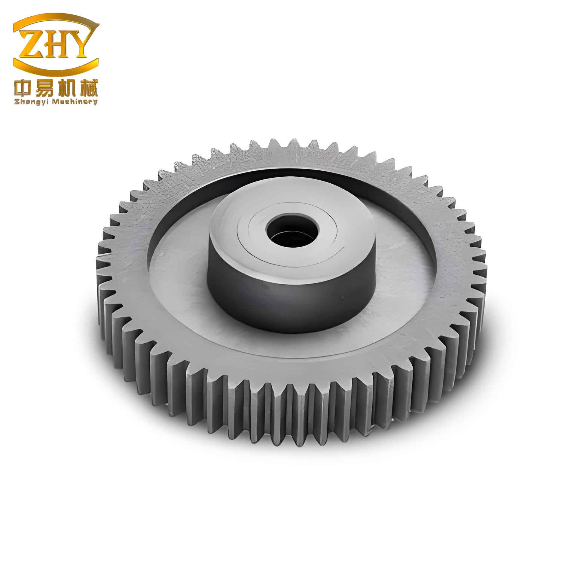
Fundamentals of Gear Geometry and Die Configuration
The subject of this investigation is a standard involute spur and pinion gear. The critical geometric parameters defining this gear are summarized in the table below, which are essential for both the final component specification and the corresponding die cavity design.
| Parameter | Symbol | Value | Unit |
|---|---|---|---|
| Module | m | 3.0 | mm |
| Number of Teeth | z | 20 | – |
| Pressure Angle | α | 25 | ° |
| Pitch Diameter | d | 60.0 | mm |
| Addendum Diameter | d_a | d + 2m = 66.0 | mm |
| Dedendum Diameter | d_f | d – 2.5m = 52.5 | mm |
| Face Width | b | 30.0 | mm |
The corresponding cold forging die assembly consists primarily of a lower die (container), an upper punch, a lower punch, and the critical gear-shaped die insert. This insert, or die cavity, features the negative impression of the final spur and pinion gear teeth. The cylindrical billet is placed within the die cavity and is compressed axially by the punches, forcing the material to flow radially outward and fill the intricate tooth profiles. The success of this process hinges on the precise design of this cavity.
Material Modeling and Process Simulation Setup
To accurately analyze the forming process, a finite element method (FEM) based simulation was conducted using DEFORM-3D software. The preparatory steps involved defining the material properties and key process parameters.
Material Properties
The workpiece material selected for this study is AISI 1045 (equivalent to Chinese grade 45 steel), a medium-carbon steel widely used for forged components due to its good balance of strength and toughness. The die material is set as AISI D3 (Cr12 type) tool steel, known for its high wear resistance and compressive strength. The essential physical and mechanical properties for simulation are tabulated below.
| Property | Workpiece (AISI 1045) | Die (AISI D3) |
|---|---|---|
| Density, ρ | 7.85 g/cm³ | 7.70 g/cm³ |
| Young’s Modulus, E | 207 GPa | 210 GPa |
| Poisson’s Ratio, ν | 0.269 | 0.30 |
| Flow Stress Model | $$\overline{\sigma} = K \cdot \overline{\varepsilon}^n$$ (Calibrated for cold working) | Rigid (in simulation) |
The plastic deformation behavior of the workpiece is governed by its flow stress curve. For cold forging conditions, the relationship is often approximated by a power-law hardening model:
$$ \overline{\sigma} = K \cdot (\overline{\varepsilon})^n $$
where $\overline{\sigma}$ is the effective flow stress, $\overline{\varepsilon}$ is the effective strain, $K$ is the strength coefficient, and $n$ is the strain-hardening exponent. For AISI 1045 under cold working, typical values are in the range of $K \approx 1000$ MPa and $n \approx 0.15-0.20$.
Process Parameters and Friction Model
The simulation parameters were set to replicate industrial cold forging conditions as closely as possible.
| Parameter | Value |
|---|---|
| Initial Billet Temperature | 25 °C (Room Temperature) |
| Punch Speed | 6.5 mm/s |
| Initial Billet Diameter | Φ52.5 mm (Matching dedendum diameter) |
| Friction Condition | Shear Friction Factor, m = 0.12 |
The friction factor of $m = 0.12$ corresponds to the use of a phosphate coating and soap lubricant, which is standard practice in cold forging to reduce friction and tool wear, facilitating the forming of complex parts like the spur and pinion gear.
Analysis of Die Cavity Structures and Their Impact
The core of this investigation revolves around three distinct die cavity designs at the apical (tooth tip) region. The primary function of an apical shunt cavity is to provide an escape volume for excess material, thereby reducing the hydrostatic pressure and the final forging load. The three designs are:
- Original Design (No Shunt Cavity): The cavity terminates precisely at the theoretical addendum circle of the gear.
- Improved Design A (Square Shunt Cavity): A small, square-shaped cavity is added beyond the addendum circle at the tip of each tooth profile.
- Improved Design B (Circular Shunt Cavity): A small, circular arc-shaped cavity is added beyond the addendum circle at the tip of each tooth profile.
The fundamental forging pressure required to fill a closed die can be conceptually described by integrating the flow stress over the deformation zone and accounting for friction and geometry complexity. A simplified expression highlighting key variables is:
$$ P_{forging} \approx \overline{\sigma}_f \cdot \left(1 + \frac{\mu \cdot A_{contact}}{h}\right) \cdot Q $$
where $\overline{\sigma}_f$ is the average flow stress, $\mu$ is the friction coefficient, $A_{contact}$ is the tool-workpiece contact area, $h$ is a characteristic height, and $Q$ is a shape factor that increases drastically with complexity (e.g., gear teeth). The shunt cavity effectively modifies the final $A_{contact}$ and the $Q$ factor by altering the material flow pattern and the final filling stage pressure.
Simulation Results: Stress Distribution and Load Analysis
The FEM simulations provide detailed insights into the effect of the shunt cavity design. The effective stress (von Mises stress) distribution at the end of the forging stroke is a critical indicator of forming difficulty and potential defect formation.
| Design | Max. Effective Stress in Gear | Core Stress | Final Forging Load | Material Fill Condition |
|---|---|---|---|---|
| No Shunt Cavity | ~930 MPa | ~880 MPa | ~1416 kN | Full fill, high pressure |
| Square Shunt Cavity | ~800 MPa | ~730 MPa | ~1151 kN | Full fill, excess material in square pocket |
| Circular Shunt Cavity | ~850 MPa | ~660 MPa | ~1049 kN | Full fill, excess material in circular pocket |
The results clearly demonstrate the efficacy of shunt cavities. Both improved designs successfully lower the maximum stress within the forged spur and pinion gear component and, more importantly, significantly reduce the required forging load. The Square Shunt Cavity achieves the lowest maximum stress (800 MPa), indicating a more uniform and less severe deformation process. However, the Circular Shunt Cavity achieves the most substantial reduction in forging load—a decrease of approximately 26% from the original design, compared to a 19% reduction for the square design.
The evolution of forging load over time, or stroke, further reveals the mechanism. The load-stroke curve for all designs follows a characteristic trend: an initial gradual rise as the billet upsets, a steeper rise as the material begins to flow into the tooth roots, and a final, very steep rise as the tooth tips are completely filled. The presence of a shunt cavity dramatically flattens this final steep section. The circular cavity performs best in this regard because its smooth, curved geometry offers less resistance to material flow compared to the sharp corners of the square cavity, which can cause localized shearing and slightly higher resistance. This is crucial for the longevity of the die used to produce the spur and pinion gear.
The analysis of material flow shows that with the circular shunt cavity, the tooth profiles are filled completely and robustly. The excess material flows smoothly into the circular pocket, ensuring no underfill defects while preventing the formation of a dead-metal zone that could lead to internal laps or folds. This complete fill is essential for the functional integrity of the meshing spur and pinion pair in service.
Comprehensive Evaluation and Optimization Strategy
While the Square Shunt Cavity yields a marginally better (lower) stress state in the part, a holistic engineering evaluation must consider multiple factors beyond a single simulation snapshot:
- Forging Load Reduction: The primary goal is to lower press tonnage requirements. The Circular Shunt Cavity is superior, offering the lowest maximum load.
- Die Stress and Fatigue Life: The lower forging load directly translates to lower mean and cyclic stresses in the die insert, potentially doubling or tripling its service life before failure or wear-based retirement.
- Material Utilization and Secondary Machining: The volume of the shunt cavity represents excess material that must be machined off in a subsequent trimming operation. The volume of a circular cavity is typically smaller than that of a square cavity designed for the same relief function, leading to less material waste and lower machining cost. This is a key economic factor in high-volume production of components like the spur and pinion gear.
- Manufacturability of the Die: A cavity with a circular profile is often easier and more precise to machine, especially via wire EDM or grinding, compared to one with sharp internal corners, which are stress concentrators and more prone to wear or cracking.
Therefore, the optimal design strategy converges on the Circular Shunt Cavity. The slight compromise in part stress is outweighed by the substantial benefits in reduced press load, extended die life, and improved overall process economy. The optimization of such a cavity can be further refined by parameterizing its geometry. The key parameters are its depth $(h_s)$ and its radius $(r_s)$. The optimal dimensions can be found by solving a constrained minimization problem, where the objective function is the forging load $(P_f)$ and the constraint is complete tooth fill without defects:
$$ \text{Minimize: } P_f(h_s, r_s) $$
$$ \text{Subject to: } V_{tooth} + V_{cavity} \leq V_{billet} – V_{flash}, \text{ and } \overline{\varepsilon}_{critical} \leq \varepsilon_{failure} $$
This can be efficiently explored through a series of designed simulation experiments (DOE).
Conclusion
The implementation of strategically designed apical shunt cavities is a highly effective method for optimizing the cold forging process of complex components such as straight-toothed cylindrical spur and pinion gears. Through detailed finite element analysis, this study quantitatively demonstrates that moving from a traditional solid die design to one incorporating a shunt cavity can reduce the maximum forging load by over 25%. While both square and circular cavities offer significant improvements over the baseline, the circular shunt cavity emerges as the superior overall design. It provides an excellent balance, offering the greatest reduction in forging tonnage—which is critical for equipment selection and die life—while also promoting smoother material flow, requiring less excess material volume, and being more manufacturable in the tooling itself. This makes the circular apical shunt cavity a recommended design feature for the cost-effective and reliable cold forging of high-quality spur and pinion gears and similar axi-symmetric components with protruding features. The methodology and conclusions presented serve as a robust foundation for the structural optimization of cold forging dies, pushing the boundaries of what can be efficiently manufactured via this advanced net-shape process.