
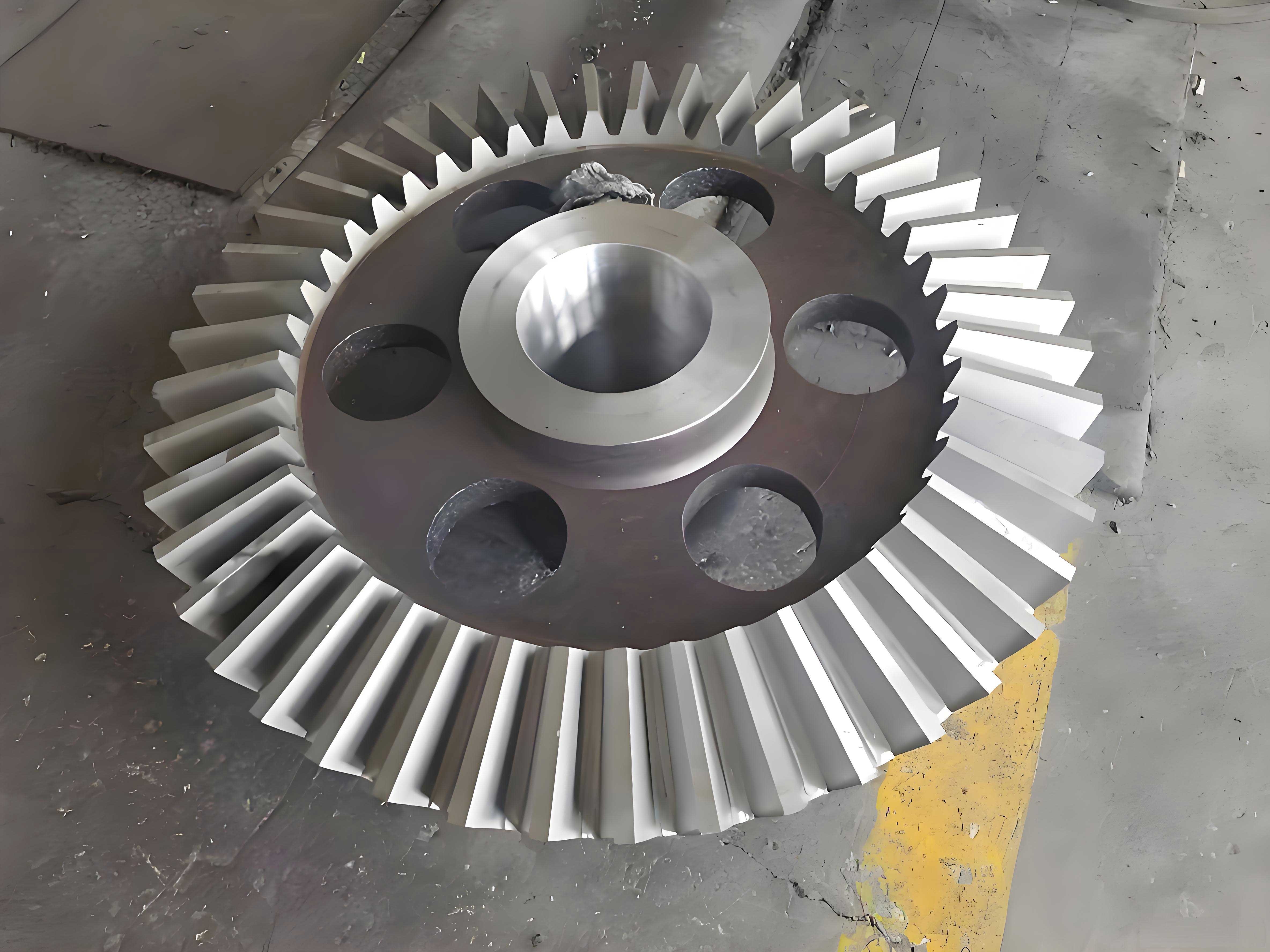
Miter gears, also known as double helical gears, are widely used in high-speed and heavy-load power transmission systems because of their high contact ratio, low axial force, high load capacity, and smooth transmission. In this study, I focus on the compound modification and meshing performance of a miter gear pair applied in a geared turbofan engine. The research includes low slip ratio parameter optimization, thermoelastic coupling analysis, compound modification tooth surface design, time-varying meshing stiffness calculation, and dynamic characteristics of the miter gear system. The miter gear pair studied here has a symmetric herringbone structure with a run-out groove between the two helical sides. The geometric and operating parameters are summarized in Table 1.
| Parameter | Sun gear | Planet gear | Ring gear |
|---|---|---|---|
| Number of teeth, z | 44 | 41 | 126 |
| Normal module, mn (mm) | 1.5 | ||
| Normal pressure angle, αn (°) | 25 | ||
| Helix angle, β (°) | 31.9218 | ||
| Normal modification coefficient, xn | 0.056 | 0.2077 | 0.47 |
| Input speed (r/min) | 7500 | ||
| Input power (kW) | 2000 | ||
I first calculate the slip ratio of the miter gear pair to evaluate the sliding power loss. The slip ratio is defined as the ratio of relative sliding velocity to tangential velocity at the contact point. For a gear pair, the slip ratios of the driving and driven gears are expressed as
$$ \eta_1 = \frac{dS_{K1} – dS_{K2}}{dS_{K1}}, \quad \eta_2 = \frac{dS_{K2} – dS_{K1}}{dS_{K2}} $$
where \(dS_{K1}\) and \(dS_{K2}\) are the arc lengths traveled by the driving and driven gears at the contact point \(K\), respectively. According to the involute parameter equation, the arc length differential can be written as
$$ dS_K = \sqrt{dx^2 + dy^2} = r_b \tan \alpha_K \, d\theta_K $$
with \(r_b\) being the base circle radius and \(\alpha_K\) the pressure angle at point \(K\). The theoretical line of action length \(L\) is given by
$$ L = \frac{m_t}{2} \sqrt{z_1^2 + z_2^2 + 2 z_1 z_2 \cos \alpha_t} $$
For the miter gear pair, the maximum slip ratios of the driving and driven gears are obtained as
$$ \eta_{1\max} = \frac{(z_1 + z_2)(\tan \alpha_{at2} – \tan \alpha_{wt})}{(z_1 + z_2)\tan \alpha_{wt} – z_2 \tan \alpha_{at2}} $$
$$ \eta_{2\max} = \frac{(z_1 + z_2)(\tan \alpha_{at1} – \tan \alpha_{wt})}{(z_1 + z_2)\tan \alpha_{wt} – z_1 \tan \alpha_{at1}} $$
where \(\alpha_{at1}\) and \(\alpha_{at2}\) are the addendum circle transverse pressure angles of the two gears, and \(\alpha_{wt}\) is the transverse working pressure angle. I analyze the influence of gear parameters on the slip ratio. Table 2 summarizes the trends when different parameters vary.
| Parameter | Variation | Effect on slip ratio |
|---|---|---|
| Helix angle β | 15° → 30° | Decreases |
| Normal pressure angle αn | 15° → 25° | Decreases |
| Normal module mn | 2 mm → 12 mm | Almost unchanged |
| Total modification coefficient Σx | −0.2 → 0.4 | Decreases |
| Gear ratio u | 31/37 → 37/31 | Slightly increases |
Based on these trends, I establish a parameter optimization model for the miter gear pair with the objective of minimizing the maximum slip ratios. The design variables include the numbers of teeth \(z_1, z_2, z_3\), normal module \(m_n\), helix angle \(\beta\), normal pressure angle \(\alpha_n\), and normal modification coefficients \(x_{n1}, x_{n2}, x_{n3}\). The objective function is
$$ \min f(\mathbf{X}) = |\eta_{1\max}| + |\eta_{2\max}| + |\eta_{3\max}| + |\eta_{4\max}| $$
subject to constraints on transmission ratio, center distance, assembly condition, undercutting, tooth tip thickness, and parameter ranges. Using a global optimization algorithm combined with branch-and-bound for discrete variables, I obtain the optimized parameters given in Table 3. The maximum slip ratios before and after optimization are compared in Table 4. The maximum slip ratio is reduced by more than 50% for the planet-ring gear pair and by about 35% for the sun-planet gear pair.
| Parameter | Sun gear | Planet gear | Ring gear |
|---|---|---|---|
| Number of teeth, z | 44 | 41 | 126 |
| Normal module, mn (mm) | 1.5 | ||
| Normal pressure angle, αn (°) | 25 | ||
| Helix angle, β (°) | 31.9218 | ||
| Normal modification coefficient, xn | 0.056 | 0.2077 | 0.47 |
| Sun-planet mesh | Planet-ring mesh | |||
|---|---|---|---|---|
| Sun | Planet | Planet | Ring | |
| Before optimization | 0.6573 | 0.6573 | 0.2765 | 0.1643 |
| After optimization | 0.4018 | 0.3408 | 0.1293 | 0.1113 |
| Reduction | 38.87% | 31.56% | 53.24% | 31.88% |
Next, I perform thermoelastic coupling analysis of the miter gear system. The heat flux on the tooth surface is calculated based on Hertz contact pressure and friction power loss. The contact pressure is
$$ p_n = \sqrt{\frac{F_n E}{2\pi (1-\mu^2) L} \frac{R_{c1} R_{c2}}{R_{c1} + R_{c2}}} $$
where \(F_n\) is the normal force, \(E\) is the elastic modulus, \(\mu\) is Poisson’s ratio, \(L\) is the contact line length, and \(R_{c1}, R_{c2}\) are the equivalent radii. The friction heat flux for the driving and driven gears is
$$ q_1 = \xi \phi \mu_f p_n v_f, \quad q_2 = (1-\xi) \phi \mu_f p_n v_f $$
with the heat partition coefficient
$$ \xi = \frac{\lambda_1 \rho_1 c_1 v_{t1}}{\lambda_1 \rho_1 c_1 v_{t1} + \lambda_2 \rho_2 c_2 v_{t2}} $$
I calculate the heat flux for the optimized and original miter gear pairs. The optimized miter gear pair has lower slip ratios, so the heat flux is significantly reduced. The convection heat transfer coefficients for the end faces and tooth surfaces are also computed. The steady-state temperature fields are solved using finite element analysis. Table 5 lists the temperatures before and after optimization. The maximum temperature rise of the sun gear, planet gear, and ring gear is reduced by 25.494°C, 8.295°C, and 12.477°C, respectively. This confirms that low slip ratio optimization effectively reduces the temperature rise of the miter gear system.
| Before optimization | After optimization | |||
|---|---|---|---|---|
| Max (°C) | Min (°C) | Max (°C) | Min (°C) | |
| Sun gear | 140.577 | 101.594 | 115.063 | 93.934 |
| Planet gear | 86.710 | 76.411 | 78.415 | 74.159 |
| Ring gear | 102.222 | 86.518 | 89.745 | 81.941 |
After the temperature field is obtained, I conduct thermoelastic coupling analysis by converting thermal elements to structural elements. The displacement results show that interference occurs at the meshing-in and meshing-out positions of the miter gear pair. The interference amounts are used to determine the tooth profile modification parameters. Table 6 gives the displacements at the meshing-in point, meshing-out point, and adjacent contact points along the line of action.
| Sun gear (μm) | Planet gear (μm) | |
|---|---|---|
| Meshing-in point displacement δei | 36.81 | 58.20 |
| Meshing-out point displacement δ’ei | 57.06 | 37.54 |
| Adjacent contact point displacement at meshing-in δc | 27.38 | — |
| Adjacent contact point displacement at meshing-out δ’c | 28.39 | — |
Based on the thermoelastic results, I calculate the compound modification parameters for the miter gear pair. The tooth profile modification amount is derived from the interference at the meshing-in and meshing-out positions. The tooth lead modification amount is determined from the axial temperature distribution. Table 7 lists the compound modification parameters used in this study. The sun and planet gears have the same modification parameters, while the ring gear is not modified.
| Parameter | Value |
|---|---|
| Lead modification amount (μm) | 10 |
| Lead modification length (mm) | 12 |
| Tooth tip modification amount (μm) | 10 |
| Tooth root modification amount (μm) | 10 |
| Tooth tip modification length (mm) | 0.46 |
| Tooth root modification length (mm) | 0.46 |
To design the compound modified tooth surface, I derive the tooth surface equation considering both profile and lead modifications. The profile modification is realized by replacing the straight rack cutter profile with a modification curve. The lead modification is achieved by controlling the grinding wheel feed motion. The coordinate systems for the rack cutter and the ground gear are established. The transverse profile of the hypothetical rack cutter consists of four segments: a straight line for the involute region, a parabolic curve for the tooth tip modification, a parabolic curve for the tooth root modification, and an elliptical arc for the root fillet. The equation of the modified profile in the cutter coordinate system \(S_0\) is expressed as
$$ \mathbf{R}_{S0} = \mathbf{M}_{0a} \mathbf{R}_{Sa} $$
where \(\mathbf{R}_{Sa}\) is the local profile equation and \(\mathbf{M}_{0a}\) is the coordinate transformation matrix. The generated tooth surface equation in the gear coordinate system \(S_2\) is obtained by the meshing condition \(\mathbf{n} \cdot \mathbf{v} = 0\). The final compound modified tooth surface equation in \(S_3\) is
$$ \mathbf{R}_{S3} = \mathbf{M}_{3a} \mathbf{M}_{at} \mathbf{R}_{S2} $$
with \(\mathbf{M}_{3a}\) representing the rotation of the gear and \(\mathbf{M}_{at}\) representing the grinding wheel feed. Using this equation, I build a parametric finite element model of the compound modified miter gear pair in ANSYS. The static contact analysis is performed for both unmodified and compound modified cases. The contact stress distributions show that the compound modification reduces the contact area and equalizes the stress. The maximum contact stress of the sun-planet mesh decreases from 1010.84 MPa to 894.73 MPa, a reduction of 11.5%. For the planet-ring mesh, it decreases from 474.15 MPa to 417.42 MPa, a reduction of 11.9%. The compound modification effectively improves the contact performance of the miter gear pair.
I then develop an analytical method to calculate the time-varying meshing stiffness of the compound modified miter gear pair. The method considers the effects of modification parameters and the run-out groove width on the contact ratio and contact state. Based on the potential energy method, the meshing stiffness of a single tooth pair is expressed as
$$ k = \frac{1}{\sum_{j=1}^{2} \left( \frac{1}{k_{tb,j}} + \frac{1}{k_{ts,j}} + \frac{1}{k_{ta,j}} + \frac{1}{k_{tf,j}} + \frac{1}{k_{ab,j}} + \frac{1}{k_{at,j}} + \frac{1}{k_{af,j}} \right) + \frac{1}{k_h}} $$
where the subscripts \(tb, ts, ta, tf, ab, at, af, h\) denote transverse bending, transverse shear, transverse compression, fillet foundation, axial bending, axial torsion, axial foundation, and Hertz contact, respectively. The transverse stiffness components are calculated by slicing the tooth along the face width. For each slice, the bending stiffness is
$$ k_{tb} = \frac{1}{\int_{x_M}^{\alpha_z} \frac{3 \cos^2 \alpha_z \, dx}{E I_x}} $$
and similar expressions are used for shear and compression. The axial bending and torsion stiffnesses are
$$ k_{ab} = \frac{1}{\int_{x_M}^{\alpha_z} \frac{\sin^2 \beta \, dx}{E I_{ax}}}, \quad k_{at} = \frac{1}{\int_{x_M}^{\alpha_z} \frac{\sin^2 \beta \, dx}{G I_p}} $$
The foundation stiffness includes the radial and axial contributions. The run-out groove affects the axial foundation stiffness. I derive the cross-sectional moment of inertia for the gear body with the run-out groove and integrate over the radius. The total meshing stiffness of the miter gear pair is obtained by summing the contributions of all contacting tooth pairs. The algorithm is verified by comparing with finite element results. The average meshing stiffness values are \(8.134 \times 10^8\) N/m for the analytical method and \(8.361 \times 10^8\) N/m for the finite element method, with an error of 2.71%.
I analyze the influence of run-out groove width, profile modification parameters, lead modification parameters, and input torque on the contact ratio and meshing stiffness. Table 8 shows the effect of run-out groove width. As the run-out groove width increases, the meshing stiffness increases, while the fluctuation value remains almost unchanged because the contact ratio is not affected.
| Run-out groove width Bt (mm) | 0 | 10 | 20 | 30 | 40 |
|---|---|---|---|---|---|
| Transverse contact ratio εα | 0.970 | 0.970 | 0.970 | 0.970 | 0.970 |
| Axial contact ratio εβ | 2.693 | 2.693 | 2.693 | 2.693 | 2.693 |
| Total contact ratio ε | 3.663 | 3.663 | 3.663 | 3.663 | 3.663 |
| Average stiffness (×108 N/m) | 8.248 | 8.349 | 8.482 | 8.624 | 8.793 |
| Stiffness fluctuation (×108 N/m) | 0.332 | 0.333 | 0.330 | 0.328 | 0.327 |
Table 9 presents the effect of profile modification amount. As the modification amount increases, the contact ratio and average meshing stiffness decrease. When the modification amount is too large, the transverse contact ratio becomes less than 1, and the stiffness fluctuation increases, which may cause meshing impact.
| Modification amount Δg (μm) | 0 | 8 | 10 | 12.5 | 14 |
|---|---|---|---|---|---|
| Transverse contact ratio εα | 1.203 | 1.126 | 1.048 | 0.970 | 0.893 |
| Axial contact ratio εβ | 2.693 | 2.693 | 2.693 | 2.693 | 2.693 |
| Total contact ratio ε | 3.896 | 3.819 | 3.741 | 3.663 | 3.586 |
| Average stiffness (×108 N/m) | 10.392 | 9.420 | 8.673 | 8.134 | 7.842 |
| Stiffness fluctuation (×108 N/m) | 0.543 | 0.256 | 0.238 | 0.342 | 0.398 |
The profile modification length also affects the meshing stiffness. Table 10 shows that as the modification length increases, the contact ratio and average stiffness decrease. The stiffness fluctuation varies with the contact ratio, and it is smaller when the contact ratio is close to an integer.
| Modification length hg (mm) | 0.6 | 0.8 | 1.0 | 1.2 |
|---|---|---|---|---|
| Transverse contact ratio εα | 1.048 | 0.981 | 0.970 | 0.893 |
| Axial contact ratio εβ | 2.693 | 2.693 | 2.693 | 2.693 |
| Total contact ratio ε | 3.741 | 3.674 | 3.663 | 3.586 |
| Average stiffness (×108 N/m) | 9.373 | 8.588 | 8.134 | 7.675 |
| Stiffness fluctuation (×108 N/m) | 0.204 | 0.215 | 0.342 | 0.478 |
For the modification curve order, Table 11 shows that higher-order curves result in larger contact ratio and average stiffness. A linear modification gives the smallest average stiffness but the largest fluctuation. The third-order curve gives the smallest fluctuation because the transverse contact ratio is close to 1.
| Curve order n | 1 | 2 | 3 | 4 | 6 |
|---|---|---|---|---|---|
| Transverse contact ratio εα | 0.738 | 0.970 | 1.028 | 1.048 | 1.126 |
| Axial contact ratio εβ | 2.693 | 2.693 | 2.693 | 2.693 | 2.693 |
| Total contact ratio ε | 3.431 | 3.663 | 3.721 | 3.741 | 3.819 |
| Average stiffness (×108 N/m) | 6.561 | 8.140 | 8.805 | 9.165 | 9.546 |
| Stiffness fluctuation (×108 N/m) | 0.874 | 0.349 | 0.178 | 0.234 | 0.319 |
For lead modification, Table 12 shows the effect of lead modification amount. As the amount increases, the axial contact ratio and average stiffness decrease. The stiffness fluctuation is smaller when the axial contact ratio is close to an integer.
| Lead modification amount Δ (μm) | 0 | 6 | 7 | 8 | 10 | 12 |
|---|---|---|---|---|---|---|
| Transverse contact ratio εα | 1.203 | 1.203 | 1.203 | 1.203 | 1.203 | 1.203 |
| Axial contact ratio εβ | 2.693 | 2.693 | 2.505 | 2.343 | 2.074 | 1.912 |
| Total contact ratio ε | 3.896 | 3.896 | 3.708 | 3.546 | 3.277 | 3.115 |
| Average stiffness (×108 N/m) | 10.392 | 10.389 | 9.749 | 8.978 | 8.169 | 7.559 |
| Stiffness fluctuation (×108 N/m) | 0.543 | 0.543 | 0.643 | 0.504 | 0.126 | 0.360 |
Table 13 shows the effect of lead modification length. Similar to the profile modification length, increasing the lead modification length reduces the contact ratio and average stiffness. The fluctuation changes with the contact ratio.
| Lead modification length h (mm) | 3 | 6 | 9 | 12 |
|---|---|---|---|---|
| Transverse contact ratio εα | 1.203 | 1.203 | 1.203 | 1.203 |
| Axial contact ratio εβ | 2.612 | 2.505 | 2.397 | 2.343 |
| Total contact ratio ε | 3.816 | 3.708 | 3.600 | 3.546 |
| Average stiffness (×108 N/m) | 10.116 | 9.755 | 9.356 | 8.978 |
| Stiffness fluctuation (×108 N/m) | 0.621 | 0.665 | 0.579 | 0.504 |
Table 14 lists the effect of lead modification curve order. Higher-order curves result in larger axial contact ratio and average stiffness. A linear modification gives the smallest fluctuation because the axial contact ratio is close to an integer, but the average stiffness is also the smallest.
| Curve order n | 1 | 2 | 3 | 4 | 6 |
|---|---|---|---|---|---|
| Transverse contact ratio εα | 1.203 | 1.203 | 1.203 | 1.203 | 1.203 |
| Axial contact ratio εβ | 2.020 | 2.343 | 2.451 | 2.505 | 2.558 |
| Total contact ratio ε | 3.223 | 3.546 | 3.654 | 3.708 | 3.762 |
| Average stiffness (×108 N/m) | 7.999 | 8.978 | 9.513 | 9.694 | 9.873 |
| Stiffness fluctuation (×108 N/m) | 0.150 | 0.504 | 0.524 | 0.489 | 0.493 |
Table 15 shows the effect of input torque. As the input torque increases, the load deformation increases, and more of the modified region enters the contact, increasing the contact ratio and average stiffness. When the torque is large enough, the contact ratio reaches its maximum and no longer changes.
| Input torque (N·m) | 200 | 300 | 400 | 500 | 600 | 700 |
|---|---|---|---|---|---|---|
| Transverse contact ratio εα | 0.893 | 0.990 | 1.048 | 1.126 | 1.203 | 1.203 |
| Axial contact ratio εβ | 2.693 | 2.693 | 2.693 | 2.693 | 2.693 | 2.693 |
| Total contact ratio ε | 3.586 | 3.683 | 3.741 | 3.819 | 3.896 | 3.896 |
| Average stiffness (×108 N/m) | 7.595 | 8.495 | 9.331 | 10.039 | 10.384 | 10.385 |
| Stiffness fluctuation (×108 N/m) | 0.467 | 0.221 | 0.240 | 0.452 | 0.564 | 0.561 |
After obtaining the time-varying meshing stiffness, I analyze the tooth surface normal load, friction force, and friction torque distribution of the miter gear pair. The normal load distribution is calculated based on the stiffness of each slice and the total meshing force. The load on each slice is proportional to its stiffness. The friction force is proportional to the normal load and the friction coefficient, and its direction depends on whether the contact point is above or below the pitch point. The friction torque is the product of the friction force and the base circle radius. The results show that the load, friction force, and friction torque are symmetric on both helical sides of the miter gear. The compound modification reduces the load-carrying area, so the load and friction force are slightly higher than those of the unmodified gear.
I then analyze the meshing phase relationships in the star miter gear system. The system has five planet gears. The meshing phase difference between the sun-planet \(i\) mesh and the sun-planet 1 mesh is
$$ \Delta t_i = T \cdot \text{mod}\left[ \frac{2}{\pi} \sqrt{a^2 – (r_{bs} + r_{bp})^2} – 2 r_{bs} + \frac{2\pi (i-1) r_{bs}}{5 p_{bt}} \right] $$
where \(T\) is the meshing period, \(a\) is the center distance, \(r_{bs}\) and \(r_{bp}\) are the base circle radii of the sun and planet gears, and \(p_{bt}\) is the transverse base pitch. Similarly, the phase difference between the sun-planet \(i\) mesh and the planet \(i\)-ring mesh is
$$ \Delta t’_i = T \cdot \text{mod}\left[ \frac{\pi r_{ap}^2 – r_{bp}^2 + \pi (r_{br} – r_{ar})^2 – r_{br}^2 + a^2 – r_{bp}^2}{p_{bt}} \right] $$
These phase differences are used to assemble the dynamic model. I establish a lumped-parameter dynamic model of the star miter gear system considering time-varying meshing stiffness, friction excitation, meshing impact, and manufacturing errors. Each gear has four degrees of freedom: three translations and one rotation. The system has 28 degrees of freedom in total. The dynamic equations are solved using the Runge-Kutta method. The dynamic meshing force and dynamic transmission error are obtained.
The results show that the compound modification reduces the vibration acceleration and the fluctuation of dynamic meshing force and transmission error. Table 16 compares the average and fluctuation values of the dynamic meshing force and dynamic transmission error before and after modification. The average dynamic meshing force remains almost unchanged, while the fluctuation is reduced by 32.4% for the sun-planet mesh and 50.1% for the planet-ring mesh. The average dynamic transmission error increases because the meshing stiffness is reduced, but the fluctuation is reduced by 64.5% and 69.5%, respectively. This indicates that compound modification effectively suppresses the vibration of the miter gear system.
| Sun-planet 1 | Planet 1-ring | |||
|---|---|---|---|---|
| Average | Fluctuation | Average | Fluctuation | |
| Unmodified meshing force (kN) | 16.272 | 3.354 | 16.271 | 3.481 |
| Modified meshing force (kN) | 16.247 | 2.311 | 16.247 | 1.738 |
| Reduction | 0.154% | 32.4% | 0.147% | 50.1% |
| Unmodified DTE (μm) | 15.437 | 3.354 | 20.473 | 3.347 |
| Modified DTE (μm) | 24.717 | 1.190 | 26.952 | 1.021 |
| Change | +37.5% | −64.5% | +24.1% | −69.5% |
In conclusion, I have conducted a comprehensive study on the compound modification and meshing performance of miter gears. The low slip ratio optimization reduces the maximum slip ratio by more than 50% for the planet-ring mesh and significantly lowers the temperature rise. The compound modification design, including both profile and lead modifications, effectively reduces contact stress and improves load distribution. The analytical meshing stiffness model considering modification and run-out groove shows good agreement with finite element results. The dynamic analysis confirms that compound modification reduces the vibration and dynamic meshing force fluctuation of the miter gear system. These findings provide a theoretical basis and engineering guidance for the design and optimization of high-speed and heavy-load miter gear systems.