
In the field of precision robotics, the rotary vector reducer stands as a critical component, dictating the performance of industrial manipulators through its transmission accuracy, stiffness, and efficiency. My research focuses on a persistent challenge: the inability to directly measure the number of meshing points between the cycloid gear and the pin wheel during operation using existing equipment. This study proposes an indirect methodology to determine the actual meshing zone by constructing a stiffness model, conducting experimental measurements, and performing theoretical inversions. The core idea is to derive the total meshing stiffness from the global torsional stiffness, thereby identifying the participating teeth and the effective meshing interval. This approach provides a more accurate constraint for tooth profile modification, which is essential for optimizing the performance of the rotary vector reducer.
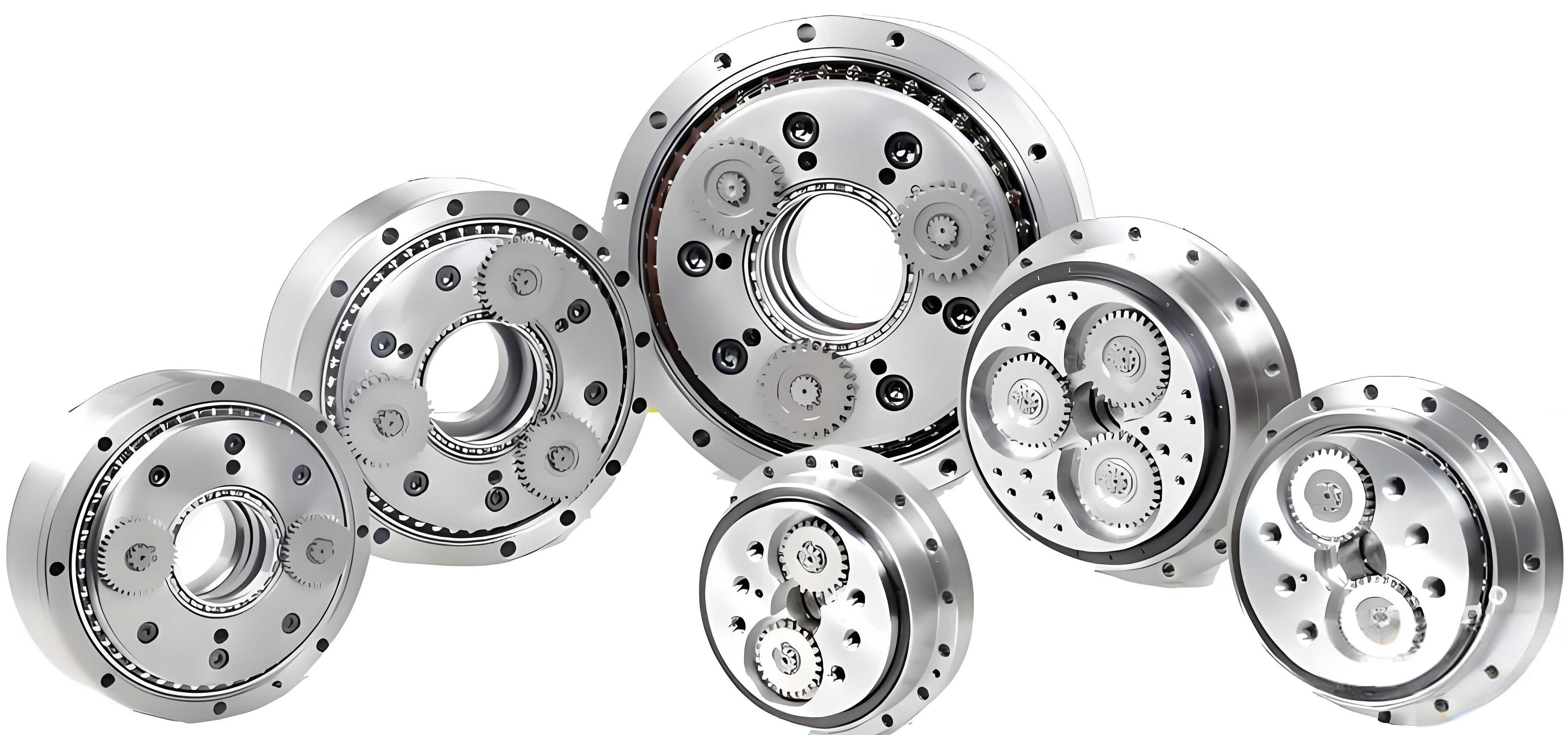
The rotary vector reducer features a two-stage transmission system. The primary stage consists of a planetary gear train, while the secondary, high-ratio stage is based on a cycloid-pin wheel mechanism. Since the deformation in the first stage is greatly reduced by the large reduction ratio of the second stage, its contribution to the overall torsional stiffness is negligible. Consequently, the global torsional stiffness of the rotary vector reducer is predominantly governed by two elements in the second stage: the contact stiffness of the needle roller bearings between the cycloid gear and the crankshafts, and the meshing stiffness between the cycloid gear and the pin wheel assembly. My analysis begins by establishing detailed mathematical models for these two key stiffness components.
The force equilibrium on the cycloid gear is complex due to its eccentric motion. The resultant force F from the pin wheel interaction provides both the tangential force for the cycloid gear’s rotation and a radial component. This force is balanced by reactions at the three crankshaft connections via needle roller bearings. The radial load on each bearing is not constant but varies with the rotation angle of the crankshaft, leading to time-varying stiffness. The relationship between the bearing radial load Fr and its radial stiffness KHc is given by an empirical formula:
$$K_{Hc} = 0.34 \times 10^4 \cdot F_r^{0.1} \cdot Z^{0.9} \cdot l^{0.8} \cdot (\cos\alpha)^{1.9}$$
where Z is the number of rollers, l is the effective roller length, and α is the contact angle (zero in this configuration). The radial force vector at each bearing (A, B, C) is a function of the tangential component Ft of the pin wheel force and the geometry:
$$\begin{cases} \mathbf{F_A} = \frac{\mathbf{F}}{3} + \frac{F_t r’_c}{3a} \begin{Bmatrix} \sin 0^\circ \\ -\cos 0^\circ \end{Bmatrix} \\ \mathbf{F_B} = \frac{\mathbf{F}}{3} + \frac{F_t r’_c}{3a} \begin{Bmatrix} \sin 120^\circ \\ -\cos 120^\circ \end{Bmatrix} \\ \mathbf{F_C} = \frac{\mathbf{F}}{3} + \frac{F_t r’_c}{3a} \begin{Bmatrix} \sin 240^\circ \\ -\cos 240^\circ \end{Bmatrix} \end{cases}$$
Here, a is the eccentricity, r’c is the cycloid gear’s pitch radius, and the resultant pin wheel force F varies with the crank angle θ: $$\mathbf{F} = F \begin{Bmatrix} \sin(\alpha_c – \theta) \\ \cos(\alpha_c – \theta) \end{Bmatrix}$$. The equivalent torsional stiffness contributed by the set of three needle roller bearings, CTHc, is calculated based on their individual stiffness values and the lever arm lc:
$$C^{T}_{Hc} = 2 (K_{HcA} + K_{HcB} + K_{HcC}) \cdot l_c^2$$
The second major component is the meshing stiffness between the cycloid gear and the pin wheel. This stiffness is highly sensitive to the meshing position, defined by the meshing phase angle θ. The curvature radius of the cycloid tooth profile at any point is a critical parameter and is given by:
$$\rho_i = \frac{r_p(1 + K’^2 – 2K’\cos\theta)^{3/2}}{K'(z_p + 1)\cos\theta – (1 + z_p K’^2)} + r_{rp}$$
In this equation, rp is the pin center circle radius, rrp is the pin radius, zp is the number of pins, and K’ is the shortened coefficient (K’ = a z_p / r_p). The curvature radius changes significantly over the potential meshing range, as illustrated conceptually by its mathematical behavior, which transitions through positive and negative values. Treating the contact as between two cylinders, Hertzian contact theory allows us to derive the local contact stiffness. The combined meshing stiffness at a single contact point j is:
$$K_{c_j} = \frac{\pi b E |\rho_i| (\rho_i – r_{rp})}{4\rho_i (1 – \mu^2) (r_{rp} + |\rho_i|)}$$
where b is the gear width, E is Young’s modulus, and μ is Poisson’s ratio. However, for the torsional stiffness of the entire rotary vector reducer, we must consider the equivalent torsional stiffness contributed by each meshing point. This depends not only on Kc but also on the square of the force arm Lj from the center of the cycloid gear to the contact point. The total equivalent torsional stiffness from all n simultaneous meshing points is:
$$C^{T}_{c} = 2 \sum_{j=1}^{n} K_{c_j} \cdot L_{j}^2$$
The factor of 2 accounts for the two cycloid gears operating in phase opposition in a standard rotary vector reducer design. The relationship between the single-point equivalent torsional stiffness and the meshing phase angle is nonlinear and central to this analysis.
Given that the needle bearing stiffness and the cycloid-pin meshing stiffness act in series within the force transmission path, the overall theoretical torsional stiffness CW of the rotary vector reducer can be modeled as:
$$C_{W} = \frac{ C^{T}_{Hc} \cdot C^{T}_{c} }{ C^{T}_{Hc} + C^{T}_{c} }$$
This model forms the theoretical foundation. To apply it, one must first obtain the actual global torsional stiffness through experiment. I utilized a dedicated rotary vector reducer comprehensive test bench. This equipment consists of a drive motor, a speed measurement system, an angular displacement measurement system, a torque measurement system, the unit under test (a rotary vector reducer), and a loading motor. It is capable of measuring transmission error, backlash, and stiffness. For this study, the input shaft of the rotary vector reducer was fixed using a specialized fixture, and torque was applied incrementally to the output flange. The corresponding angular displacement was recorded with high-precision sensors. Testing a common RV-40E type rotary vector reducer, I applied torque from 0 N·m up to its rated torque of 412 N·m, then reversed the loading direction down to -412 N·m to account for hysteresis. The resulting torque-angle curve forms a closed loop, with the average slope of the loading and unloading curves representing the measured torsional stiffness. At the rated torque, the measured global stiffness CW was found to be approximately 3.06 × 10⁸ N·mm/rad.
With the experimental global stiffness value in hand, the next step is the逆向求解 (inverse solution) to find the meshing zone. The theoretical model relates CW to CTHc and CTc. Using the derived formulas for bearing stiffness under load and the known geometrical and material parameters of the RV-40E reducer, I first calculated the equivalent torsional stiffness of the needle bearing assembly, CTHc, for the operating condition. Then, via the series stiffness formula, I solved for the total equivalent torsional stiffness stemming from the cycloid-pin meshing: CTc ≈ 6.24 × 10⁸ N·mm/rad. This value is the theoretical target that the sum of contributions from individual meshing points must reach.
A fundamental characteristic of the cycloid-pin engagement in a rotary vector reducer is that the meshing points are consecutive pins. Therefore, to identify the actual meshing zone, I systematically calculated the contribution of every possible consecutive set of pins. Over a 180° meshing phase range, there are theoretically 21 potential contact points. For each pin position j, I computed the single-point equivalent torsional stiffness KTC_j = 2 \cdot K_{c_j} \cdot L_{j}^2 (the factor of 2 for two cycloid gears is included here for the total system). The results are summarized in the following table, which is crucial for the zone identification process.
| Pin Number (j) | Meshing Phase Angle θ (°) Approx. | Single-Point Equivalent Torsional Stiffness, KTC_j (N·mm/rad) |
|---|---|---|
| 1 | ~0 | 0 |
| 2 | ~9 | 2.20 × 10⁶ |
| 3 | ~18 | 1.97 × 10⁷ |
| 4 | ~27 | 1.33 × 10⁸ |
| 5 | ~36 | 1.84 × 10⁸ |
| 6 | ~45 | 1.76 × 10⁸ |
| 7 | ~54 | 1.66 × 10⁸ |
| 8 | ~63 | 1.52 × 10⁸ |
| 9 | ~72 | 1.38 × 10⁸ |
| 10 | ~81 | 1.22 × 10⁸ |
| 11 | ~90 | 1.06 × 10⁸ |
| 12 | ~99 | 8.93 × 10⁷ |
| 13 | ~108 | 7.33 × 10⁷ |
| 14 | ~117 | 5.79 × 10⁷ |
| 15 | ~126 | 4.38 × 10⁷ |
| 16 | ~135 | 3.12 × 10⁷ |
| 17 | ~144 | 2.03 × 10⁷ |
| 18 | ~153 | 1.16 × 10⁷ |
| 19 | ~162 | 5.25 × 10⁶ |
| 20 | ~171 | 1.33 × 10⁶ |
| 21 | ~180 | 0 |
The identification process involves summing the stiffness contributions of consecutive pins, starting from various points, until the total approximates the target CTc value of 6.24 × 10⁸ N·mm/rad. After performing these calculations, I found that the sum of contributions from pins 6, 7, 8, and 9 yields a total of approximately 6.32 × 10⁸ N·mm/rad. This is the closest match to the theoretical target. This corresponds to a meshing phase angle interval of approximately 54° to 81°. Therefore, the analysis indicates that under the rated load, the actual meshing zone in this rotary vector reducer involves four consecutive pins (n=4) within that specific angular range. This finding is more precise than the commonly assumed broader intervals like 25° to 100° and resolves the conflict with the typical expected meshing point count of 4 to 7.
To validate the theoretical and analytical findings regarding the meshing zone in the rotary vector reducer, I conducted a finite element analysis (FEA). A detailed model of the cycloid gear and pin wheel assembly was constructed, incorporating material properties and contact definitions. A torque of 412 N·m was applied to the cycloid gear, and contact conditions were enabled for all potential pin locations. The FEA solution clearly showed that the contact pressure and force transmission were concentrated on pins numbered 6 through 9, with negligible force on the other pins. This result perfectly aligns with the meshing zone identified through the stiffness inversion method. The finite element analysis thus provides strong independent confirmation of the correctness of the theoretical stiffness model and the proposed methodology for determining the meshing interval in a rotary vector reducer.
In conclusion, this research presents a robust framework for investigating the meshing characteristics of rotary vector reducers without direct measurement of contact points. The key contributions are threefold. First, I developed a comprehensive stiffness model that accounts for the time-varying nature of needle roller bearing stiffness and the position-dependent meshing stiffness of the cycloid-pin engagement. The model effectively links these local stiffnesses to the global torsional stiffness of the rotary vector reducer. Second, through precise experimental measurement on a dedicated test bench, I obtained the actual global torsional stiffness under operational load. Using the model inversely, I derived the total meshing stiffness and subsequently identified the specific consecutive pins involved in load sharing by matching summed contributions to the derived value. For the tested rotary vector reducer, this zone was pinpointed to a phase angle of 54° to 81°, corresponding to four pins. Third, the results were rigorously validated using finite element analysis, which confirmed the identified meshing zone. This methodology offers a powerful tool for providing accurate constraints for cycloid gear tooth profile modification. By ensuring the design and modification are based on the real load-sharing zone, the performance of the rotary vector reducer—including its stiffness, efficiency, and longevity—can be significantly optimized. Future work could involve extending this method to study the meshing zone under dynamic conditions or different loading patterns, further enhancing the design and application of rotary vector reducers in high-precision robotics.
The implications of accurately determining the meshing zone are profound for the design and manufacturing of rotary vector reducers. Traditional profile modification methods often rely on assumed zones, which can lead to suboptimal performance. The stiffness-based approach detailed here provides a data-driven way to define the modification interval. For instance, if the goal is to maximize torsional stiffness, modification efforts should be focused primarily on the tooth segments that correspond to the identified meshing zone (e.g., pins 6-9). Conversely, areas outside this zone, which experience little to no load under normal operation, can be modified differently to minimize backlash or reduce friction without compromising strength. This precision allows engineers to tailor the tooth profile more effectively, potentially achieving a better balance between competing performance指标 such as stiffness, efficiency, and rotational accuracy. Furthermore, the methodology is not limited to a single model; it can be adapted to various sizes and designs of rotary vector reducers by inputting their specific geometric and material parameters into the stiffness models. This universality makes it a valuable asset in the development and quality assurance of next-generation rotary vector reducers for advanced robotic systems.
To further elaborate on the mathematical intricacies, let’s consider the sensitivity of the results. The target value for the total meshing stiffness CTc is sensitive to the measured global stiffness CW and the calculated bearing stiffness CTHc. A small error in the experimental measurement can shift the target. Therefore, high-precision measurement systems are essential. The bearing stiffness formula itself, being empirical, introduces some uncertainty. A more detailed model of the needle roller bearing, perhaps incorporating full raceway compliance, could refine this component. Regarding the meshing stiffness, the Hertzian formula assumes semi-infinite bodies and perfect geometry. In reality, surface roughness and localized plastic deformation might cause minor deviations. However, the excellent agreement with FEA suggests that for engineering purposes, the models are sufficiently accurate. The process can be summarized in a systematic flowchart, but the core equations remain as presented. This study underscores the importance of an integrated approach combining theoretical modeling, experimental validation, and computational simulation in advancing the understanding and design of complex mechanical systems like the rotary vector reducer.