
The design of spiral gears for low-power, non-parallel shaft drives presents a unique set of challenges and opportunities. While prized for their simplicity and low manufacturing cost, making them prevalent in textile, light industry, printing, and food processing machinery, traditional design approaches have often been confined to kinematic and geometric calculations. This methodology neglects critical performance metrics such as operational efficiency, service life via wear reduction, and the overall weight and size of the transmission unit. This article comprehensively investigates the optimal selection of the key design parameter—the helix angle—from the integrated perspectives of maximizing efficiency, minimizing wear, and achieving the lightest possible construction. The central thesis is that a deliberate and synergistic choice of helix angles for the pinion and gear can elevate spiral gear design from a mere kinematic exercise to a performance-optimized engineering solution.
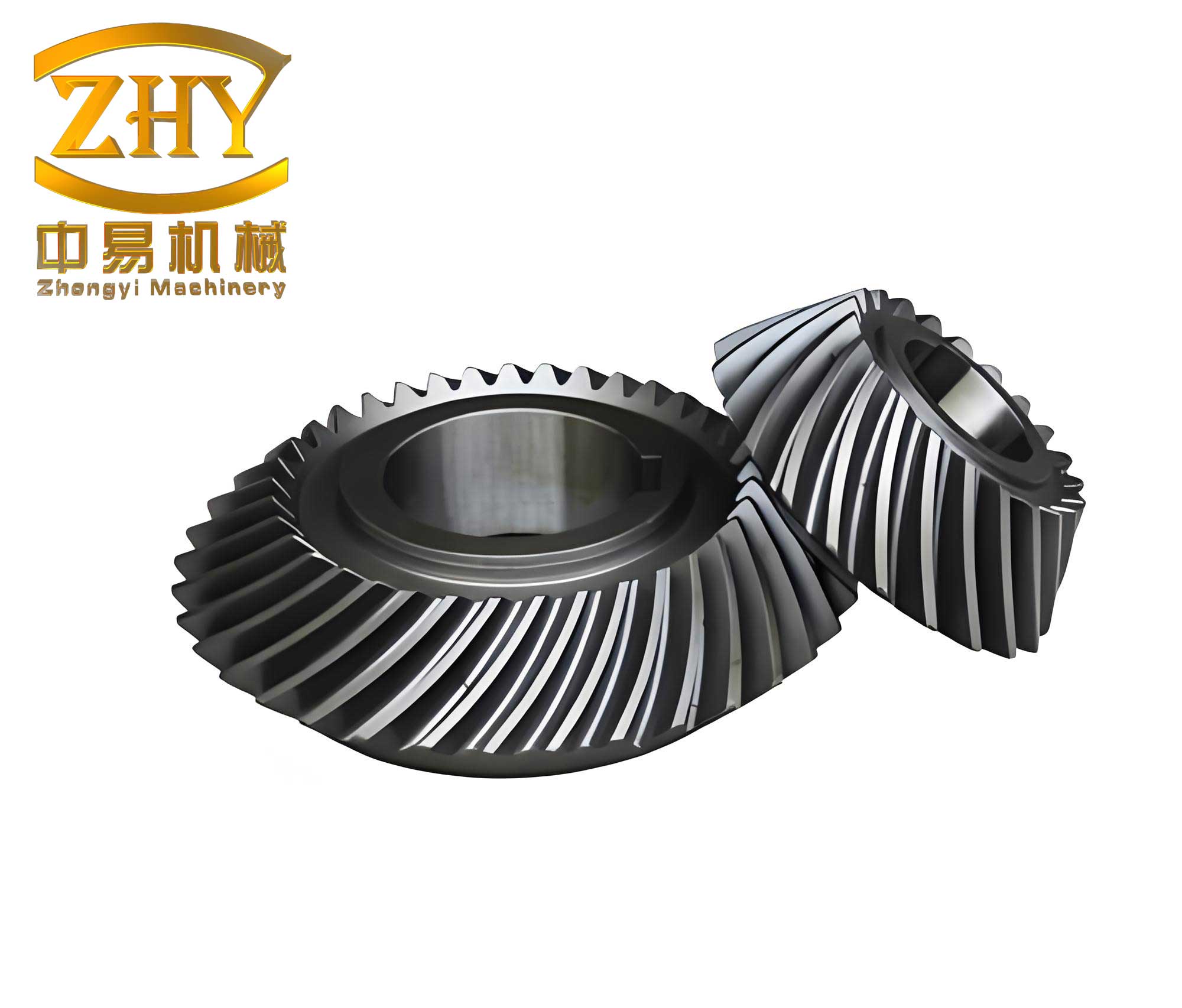
The fundamental geometry of a spiral gear pair involves two essential angles: the pinion helix angle $\beta_1$ and the gear helix angle $\beta_2$. The shaft angle $\Sigma$, the angle between the two rotating axes, is determined by the combination of these helix angles. There are four primary geometric configurations for a spiral gear drive, defined by the relationship between $\Sigma$, $\beta_1$, and $\beta_2$:
- Both gears have the same hand (e.g., both right-handed): $\Sigma = \beta_1 + \beta_2$.
- Both gears have opposite hands: $\Sigma = |\beta_1 – \beta_2|$.
The choice among these configurations, along with the magnitude of the helix angles, has profound implications for the drive’s performance. The analysis begins with the most critical operational metric: efficiency.
I. Influence of Helix Angle on Meshing Efficiency
The meshing of a spiral gear pair can be conceptually analyzed as the interaction between a spiral gear and a helical rack. At the pitch point P, the pinion (gear 1) with velocity $v_1$ drives the equivalent rack (gear 2) with velocity $v_2$. The relative sliding velocity $v_s$ along the tooth’s spiral direction is the vector difference between these velocities. The power loss due to sliding friction along this line of action is the dominant source of inefficiency, with losses in the profile direction being comparatively negligible.
If $F_t$ is the tangential driving force at the pitch point, the useful output power is $P_{out} = F_t \cdot v_2$. The friction power loss is $P_{loss} = f_v \cdot F_n \cdot v_s$, where $f_v$ is the coefficient of sliding friction and $F_n$ is the normal force. The input power is the sum: $P_{in} = F_t \cdot v_2 + f_v F_n v_s$. The meshing efficiency $\eta$ is therefore:
$$
\eta = \frac{P_{out}}{P_{in}} = \frac{F_t v_2}{F_t v_2 + f_v F_n v_s}
$$
Through geometric relations involving the helix angles and the pressure angle $\alpha_n$, the normal force can be related to the tangential force: $F_n = F_t / (\cos \alpha_n \cos \beta)$. Incorporating the concept of a virtual coefficient of friction $f_v’ = f_v / \cos \alpha_n$ and the kinematic relation $v_s = v_1 \frac{\sin \Sigma}{\cos \beta_2}$ (for certain configurations), the efficiency formula can be distilled to a function of the fundamental angles. A generalized approximate expression for the meshing efficiency of a spiral gear pair is:
$$
\eta \approx \frac{1}{1 + f_v’ \cdot \frac{v_s}{v_2}} = \frac{1}{1 + f_v’ \cdot \frac{\sin \Sigma}{\sin(\Sigma \mp \beta_1)}}
$$
Where the sign in the denominator depends on the specific hand combination. This reveals that efficiency $\eta$ is influenced by the virtual friction $f_v’$, the shaft angle $\Sigma$, and the pinion helix angle $\beta_1$. To find the condition for maximum efficiency, we treat $\Sigma$ and $f_v’$ as constants and analyze $\eta$ as a function of $\beta_1$. The analysis yields a crucial result: Maximum efficiency occurs only in the configuration where both spiral gears have the same hand of helix ($\Sigma = \beta_1 + \beta_2$) and when the pinion helix angle is half the shaft angle:
$$
\beta_1 = \beta_2 = \frac{\Sigma}{2}
$$
At this specific condition, the first derivative of the efficiency function with respect to $\beta_1$ is zero, and the second derivative confirms a maximum. For the other three combinations ($\Sigma = |\beta_1 – \beta_2|$), no such maximum exists within the practical range of angles. Therefore, the first rule for optimal spiral gear design is to employ same-hand helices and strive for equal angles.
| Design Goal | Recommended Configuration | Optimal Helix Angle Condition | Efficiency Trend |
|---|---|---|---|
| Maximize Efficiency | Same-hand helices ($\Sigma = \beta_1 + \beta_2$) | $\beta_1 = \beta_2 = \Sigma / 2$ | Peak efficiency achieved |
| – | Opposite-hand helices | Any | Lower efficiency, no maximum |
II. Influence of Helix Angle on Wear and Sliding Velocity
Wear in gear teeth is predominantly governed by the sliding velocity and the lubrication condition. In a spiral gear pair, contact occurs at a theoretical point, leading to very high contact stresses. Unlike worm gears where a favorable oil wedge can form at high sliding angles, the point contact in spiral gears severely limits the formation of a full elastohydrodynamic lubrication film. Consequently, the friction regime is often boundary or mixed, and the effective coefficient of friction $f_v’$ tends to increase with increasing sliding velocity $v_s$ due to localized heating and potential adhesive wear.
Thus, minimizing the sliding velocity $v_s$ is paramount for reducing wear and extending the life of the spiral gear set. The sliding velocity is given by:
$$
v_s = \frac{v_1 \sin \Sigma}{\cos \beta_2}
$$
For a fixed input speed (and thus fixed $v_1$) and a fixed shaft angle $\Sigma$, $v_s$ is minimized by maximizing $\cos \beta_2$, which means minimizing the gear helix angle $\beta_2$. Referring back to the configurations, we find that for the same-hand setup ($\Sigma = \beta_1 + \beta_2$), a small $\beta_2$ implies a larger $\beta_1$ (since $\Sigma$ is fixed). However, in the opposite-hand setup ($\Sigma = |\beta_1 – \beta_2|$), a small $\beta_2$ can be achieved while also keeping $\beta_1$ small. This creates a trade-off: the opposite-hand configuration can offer lower sliding velocities (and thus potentially less wear) than a poorly chosen same-hand setup, but at the cost of significantly lower efficiency as established earlier.
A detailed analysis of the ratio $v_s / v_1$ provides clear guidance. For the same-hand configuration, as $\beta_1$ increases from a small value, $v_s$ initially decreases rapidly and then stabilizes. There exists a “low-wear zone” where $v_s$ is relatively insensitive to changes in $\beta_1$. Selecting a $\beta_1$ in this stable region is advisable. Crucially, if the shaft angle $\Sigma$ is large, choosing $\beta_1$ near 0° (which forces $\beta_2 \approx \Sigma$) leads to an extremely high $v_s/v_1$ ratio and catastrophic wear, and must be avoided. The following table illustrates the sliding velocity characteristics for the same-hand configuration with $\Sigma = 90^\circ$.
| Pinion Helix Angle $\beta_1$ (deg) | Gear Helix Angle $\beta_2$ (deg) ($\Sigma=90^\circ$) | Relative Sliding Velocity $v_s / v_1$ | Wear Implication |
|---|---|---|---|
| 10 | 80 | ~1.52 | Very High Wear |
| 30 | 60 | ~1.00 | High Wear |
| 45 | 45 | ~0.71 | Moderate (Optimal Efficiency Point) |
| 60 | 30 | ~0.58 | Lower Wear (Stable Zone) |
| 75 | 15 | ~0.52 | Low Wear (Stable Zone) |
Attempting to reverse the output direction by switching to opposite-hand helices is particularly detrimental. It dramatically increases both $v_s$ and $f_v’$, leading to a sharp drop in efficiency and a severe increase in wear, making this method generally unacceptable except for very small, intermittent drives.
III. Influence of Helix Angle on System Weight
Minimizing the weight and bulk of a spiral gear transmission is often desirable, especially in portable or aerospace applications. The total material volume of the two gears is a primary contributor. Assuming constant face width $b$, module $m_n$, number of teeth $z_1$ and $z_2$, and pinion pitch diameter $d_1 = m_n z_1 / \cos \beta_1$, the total volume $V_{total}$ can be expressed as proportional to the sum of the squares of the pitch diameters. Simplifying, we get a volume function $V$ proportional to:
$$
V \propto \frac{1}{\cos^2 \beta_1} + \frac{1}{\cos^2 \beta_2}
$$
For the same-hand configuration ($\Sigma = \beta_1 + \beta_2$), with $\Sigma$ constant, $\beta_2 = \Sigma – \beta_1$. Substituting and taking the partial derivative of $V$ with respect to $\beta_1$ and setting it to zero yields the condition for minimum volume:
$$
\frac{\sin \beta_1}{\cos^3 \beta_1} = \frac{\sin(\Sigma – \beta_1)}{\cos^3(\Sigma – \beta_1)}
$$
The solution to this equation is, once again:
$$
\beta_1 = \beta_2 = \frac{\Sigma}{2}
$$
Remarkably, the condition for minimum weight coincides exactly with the condition for maximum efficiency. A plot of $V$ versus $\beta_1$ for different $\Sigma$ values produces a family of “minimum weight curves” that pass through the point $\beta_1 = \Sigma/2$. While selecting a point on this curve gives the absolute minimum weight, the curve is relatively flat near the minimum. This allows some deviation to accommodate other constraints (like moving into the low-wear stable zone) without a significant weight penalty.
For the opposite-hand configuration ($\Sigma = |\beta_1 – \beta_2|$), the volume function does not exhibit a clear minimum within the practical range; it generally decreases as both angles become smaller. However, this configuration sacrifices efficiency and often increases wear. For the purpose of weight reduction, the same-hand configuration with balanced helix angles is superior.
| Configuration | Condition for Min. Weight | Coincides with Max. Efficiency? | Practical Implication |
|---|---|---|---|
| $\Sigma = \beta_1 + \beta_2$ | $\beta_1 = \beta_2 = \Sigma/2$ | Yes | Optimal for weight & efficiency. |
| $\Sigma = |\beta_1 – \beta_2|$ | No distinct minimum | No | Not advantageous for weight optimization. |
IV. Influence of Helix Angle on Bearing Size
Helical and spiral gears generate axial forces $F_a = F_t \tan \beta$, where $F_t$ is the tangential force. These axial forces must be supported by the shaft bearings, directly influencing their size, lifespan, and the design of bearing housings. Using angular contact ball bearings (e.g., 7000C type) as a common choice, we can analyze how the helix angle $\beta$ affects the required bearing dynamic load rating $C$, which is a proxy for bearing size.
Consider a shaft supporting a driven spiral gear with helix angle $\beta_2$, subjected to circumferential force $F_{t2}$. The axial force is $F_{a2} = F_{t2} \tan \beta_2$. The bearing reactions are calculated from statics, considering both radial and axial loads. For a given bearing arrangement (face-to-face or back-to-back), speed $n$, required lifespan $L_h$, and reliability factor, the required dynamic load rating $C$ is calculated from the equivalent dynamic bearing load $P$ using the standard formula:
$$
C = P \left( \frac{60 n L_h}{10^6} \right)^{1/3}
$$
The equivalent load $P$ for an angular contact bearing is $P = X F_r + Y F_a$, where $F_r$ and $F_a$ are the radial and axial loads on the bearing, and $X$, $Y$ are coefficients. Both $F_r$ and $F_a$ are functions of $F_{t2}$ and $\beta_2$. A detailed force analysis shows that the required $C$ for both the left and right bearings is a function of $\tan \beta_2$ and the shaft angle $\Sigma$.
For the same-hand configuration, analysis reveals that for a fixed $\Sigma$ and $F_t$, the required bearing capacity $C$ initially decreases as $\beta_2$ increases from a small value, then gradually levels off. The curves are flatter for smaller shaft angles $\Sigma$. This indicates that selecting a larger helix angle (within the stable, low-wear zone identified earlier) not only benefits wear but also leads to smaller required bearing sizes. The following data exemplifies the trend for the bearing supporting the driven gear in a same-hand setup.
| Driven Gear Helix $\beta_2$ (deg) | Axial Force $F_{a2} / F_{t2}$ | Trend in Req’d Bearing Rating $C$ | Bearing Size Implication |
|---|---|---|---|
| 15 | 0.27 | Higher | Larger bearings required |
| 30 | 0.58 | Medium | Moderate size |
| 45 | 1.00 | Lower (Stable Region) | Smaller, stable sizing |
| 60 | 1.73 | Low (Stable Region) | Smaller, stable sizing |
Thus, a larger helix angle, while increasing the axial force in absolute terms, can lead to a more favorable distribution of forces on the bearings, ultimately reducing the size-determining equivalent dynamic load. This provides a third incentive (after efficiency-weight and wear) to select helix angles in the higher, stable region (e.g., $\beta_1 = 60^\circ$, $\beta_2 = 30^\circ$ for $\Sigma=90^\circ$) rather than at the theoretical optimum of 45°.
V. Comprehensive Guidelines for Optimal Helix Angle Selection
Synthesizing the analyses from all four perspectives—efficiency, wear, weight, and bearing size—provides a clear, hierarchical set of guidelines for the optimal design of spiral gear drives.
Primary Guideline: Always prefer the configuration with same-hand helix angles ($\Sigma = \beta_1 + \beta_2$). This configuration is the only one that allows for a true maximum in efficiency and a minimum in system weight. It also permits operation in a region of acceptably low sliding velocity and favorable bearing loading.
Secondary Guideline (Target Selection): The ideal theoretical target is to set both helix angles equal to half the shaft angle: $\beta_1 = \beta_2 = \Sigma / 2$. This point simultaneously delivers maximum efficiency and minimum weight. It also simplifies manufacturing, as both gears can be cut using the same machine setup and differential gear train.
Tertiary Guideline (Practical Refinement): Consider deviating from the theoretical target ($\Sigma/2$) towards a slightly larger pinion angle $\beta_1$ and a correspondingly smaller gear angle $\beta_2$, while keeping $\Sigma$ constant. For example, if $\Sigma = 90^\circ$, instead of $\beta_1 = \beta_2 = 45^\circ$, consider $\beta_1 = 60^\circ$, $\beta_2 = 30^\circ$. This adjustment moves the design into the “stable zone” where:
- Sliding velocity $v_s$ is lower and less sensitive to angle variations, reducing wear.
- The required bearing size is minimized or stabilized.
- The sacrifice in efficiency and increase in weight from the theoretical optimum are relatively small, as both functions are flat near the peak/minimum.
Guidelines to Avoid:
- Avoid using opposite-hand helix angles ($\Sigma = |\beta_1 – \beta_2|$) solely to reverse the direction of rotation. The severe penalties in efficiency and wear make this method impractical for most applications.
- Avoid selecting very small helix angles (especially on the gear) in same-hand configurations when $\Sigma$ is large. This leads to extremely high sliding velocities, rapid wear, and large bearing requirements.
- Do not arbitrarily choose helix angles to meet a predefined center distance. First, apply the above principles to select optimal $\beta_1$ and $\beta_2$. Then, adjust the normal module $m_n$ and number of teeth $z_1, z_2$ to achieve the required center distance $a = \frac{m_n}{2 \cos \beta_1} (z_1 + \frac{z_2 \cos \beta_1}{\cos \beta_2})$.
By following this integrated approach, designers can transform the standard spiral gear from a simple motion-transmitting component into a highly optimized element of a mechanical system, balancing longevity, energy consumption, and spatial economy.