
Spur gears are fundamental components in a vast array of mechanical transmission systems, prized for their straightforward design, manufacturing ease, and high power transmission efficiency. Their performance directly influences the overall efficiency, reliability, noise level, and lifespan of machinery. In demanding applications such as tunneling machine reducers, gear pairs operate under harsh conditions involving heavy loads, impacts, and potential misalignments. These factors can lead to deviations from the ideal conjugate meshing principle, resulting in edge loading, stress concentration at the tooth ends, and severe meshing impacts. These phenomena precipitate increased vibration, noise, and accelerated wear. To mitigate these issues and enhance the dynamic performance and durability of spur gear transmissions, tooth profile modifications, particularly lead crowning, are extensively employed in industrial practice. This article delves into the mathematical modeling of crowned tooth surfaces and conducts a detailed three-dimensional dynamic contact analysis to elucidate the effects of lead crown modification on the meshing behavior of spur gears.
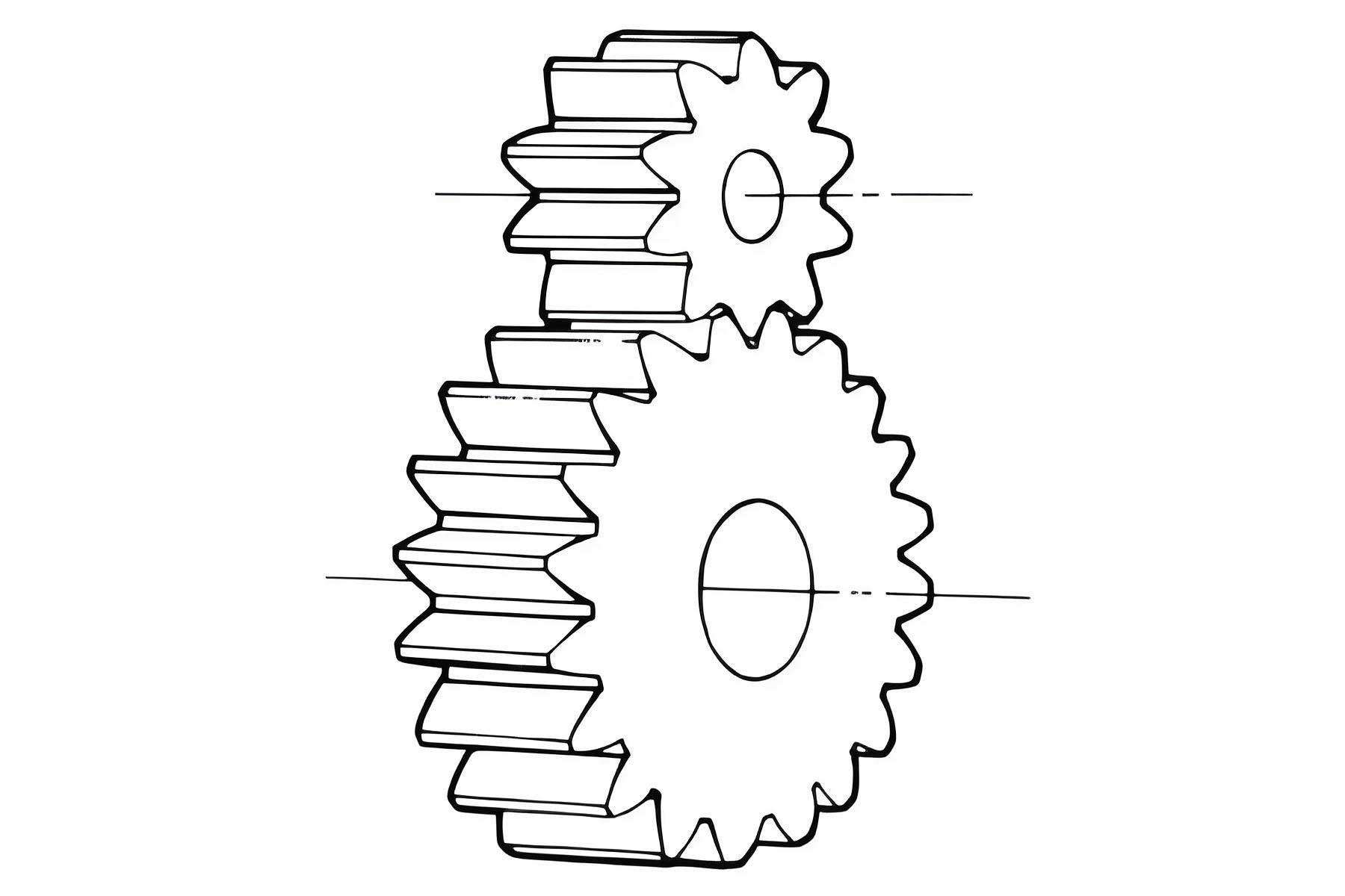
The geometric foundation of a standard spur gear is defined by its basic parameters. For the purpose of this analysis, we consider a spur gear pair with parameters typical for a heavy-duty application. These parameters are summarized in the table below.
| Parameter | Pinion | Gear |
|---|---|---|
| Number of Teeth (z) | 18 | 23 |
| Module (mn) [mm] | 6 | |
| Pressure Angle (αn) [°] | 20 | |
| Face Width (b) [mm] | 50 | 50 |
| Addendum Coefficient (ha*) | 1.0 | |
| Dedendum Coefficient (c*) | 0.25 | |
Lead crowning is a modification applied along the tooth width direction. Instead of a perfect cylindrical surface, the tooth flank is given a slight barrel shape. This is typically achieved by modifying the rack cutter profile used in the gear generation process. The crowning amount, denoted as Cc, is the maximum deviation at the center of the tooth face from the theoretical straight line. The crowning profile is often defined by a circular arc. The modification can be pure crowning (applied across the entire face width) or end relief (applied only near the ends). For this study, we focus on pure lead crowning applied to the pinion of the spur gear pair.
The mathematical generation of a crowned spur gear tooth surface begins with defining the surface of the generating rack cutter. A coordinate system is attached to the rack cutter. The tooth profile of the rack consists of several segments: the addendum straight line, the fillet curve, and the dedendum straight line. To incorporate lead crowning, the rack tooth is considered to have a variable profile shift along its width, following a circular arc. The position vector of a point on the rack cutter surface ΣR1 in the rack coordinate system O1x1y1z1 can be expressed as:
$$
\mathbf{R_1}(u, l) =
\begin{cases}
x_1 = u \cdot \sin\alpha_n \\
y_1 = l \\
z_1 = -u \cdot \cos\alpha_n + (h_{a}^* m_n + C_c(l))
\end{cases}
\quad \text{for the addendum flank}
$$
$$
\mathbf{R_1}(\theta, l) =
\begin{cases}
x_1 = \rho \sin\theta – \rho \sin\alpha_n \\
y_1 = l \\
z_1 = -\rho \cos\theta + \rho \cos\alpha_n + (h_{a}^* m_n – \rho (1 – \sin\alpha_n))
\end{cases}
\quad \text{for the fillet}
$$
Here, \(u\) and \(\theta\) are the surface parameters for the straight and fillet segments, respectively. \(l\) is the coordinate along the rack width (aligned with the future gear face width). The crowning function \(C_c(l)\) defines the modification. For a symmetrical circular arc crowning with maximum crowning \(C_c\) at the center (\(l=0\)), the function is:
$$
C_c(l) = C_c \left( 1 – \sqrt{1 – \left(\frac{l}{r_e}\right)^2} \right) \approx \frac{C_c}{2 r_e^2} l^2
$$
where \(r_e\) is the radius of the crowning arc, related to the face width \(b\) and crowning amount \(C_c\) by \( r_e = \frac{(b/2)^2 + C_c^2}{2 C_c} \). The approximation is valid for small crowning amounts relative to the face width.
The next step involves defining the coordinate transformation between the moving rack cutter and the rotating gear blank. The meshing process between the rack and the gear is a generating motion: the rack translates, and the gear blank rotates, simulating the rolling of the gear’s pitch circle on the rack’s pitch line without slip. The relationship is governed by:
$$
y_1 = r \phi
$$
where \(r\) is the pitch radius of the spur gear (\(r = m_n z / 2\)) and \(\phi\) is the rotation angle of the gear.
The fundamental equation of meshing states that for a point on the rack to be a contact point on the generated gear surface, the relative velocity vector between the two surfaces at that point must lie in the common tangent plane. Mathematically, this is expressed as the scalar product of the relative velocity and the surface normal being zero:
$$
\mathbf{n} \cdot \mathbf{v}^{(12)} = 0
$$
The unit normal vector \(\mathbf{n}\) to the rack surface is found from the partial derivatives of \(\mathbf{R_1}\). The relative velocity \(\mathbf{v}^{(12)}\) is derived from the kinematic relationship between the rack and the gear. Applying this condition to the rack surface equations yields the specific meshing function that links the surface parameters (\(u\) or \(\theta\), \(l\)) and the gear rotation angle \(\phi\). For the straight flank segment, the meshing condition simplifies to:
$$
\phi(u, l) = \frac{1}{r} \left( l + \frac{u \cos\alpha_n}{\tan\alpha_n} \right)
$$
A similar, though more complex, relationship is obtained for the fillet segment. Finally, the generated crowned spur gear tooth surface \(\Sigma_2\) in the gear coordinate system is obtained by applying the coordinate transformation matrix \(\mathbf{M}_{21}(\phi)\) to the rack surface point \(\mathbf{R_1}\) that satisfies the meshing equation:
$$
\mathbf{R_2}(u, l) = \mathbf{M}_{21}(\phi(u, l)) \cdot \mathbf{R_1}(u, l)
$$
where the transformation matrix accounts for both the translation and rotation of the gear blank relative to the rack. By discretizing the parameters \(u\) and \(l\) and solving these equations, a point cloud representing the precise crowned tooth flank of the spur gear is generated. This mathematical model is the cornerstone for creating accurate computer-aided design (CAD) models for subsequent analysis.
To perform a dynamic analysis, a three-dimensional solid model of the crowned spur gear pair is essential. The point cloud data generated from the mathematical model is imported into CAD software. Surfaces are fitted through these points, and the solid tooth volume is created by stitching these surfaces and performing Boolean operations with the gear body. For comparison, an unmodified spur gear pair model is also created using standard involute geometry. The focus of the lead crowning modification is applied to the pinion, while the gear remains unmodified.
The dynamic performance of the spur gear pair is investigated using the explicit dynamic finite element method. This technique is particularly suited for simulating transient events, high-speed dynamics, and complex contact interactions, such as those occurring during gear meshing impacts. The governing equation for the dynamic contact problem is:
$$
\mathbf{M}_p \ddot{\mathbf{u}}_p + \mathbf{C}_p \dot{\mathbf{u}}_p + \mathbf{K}_p \mathbf{u}_p = \mathbf{P}_p(t) + \mathbf{F}_p(t) \\
\mathbf{M}_g \ddot{\mathbf{u}}_g + \mathbf{C}_g \dot{\mathbf{u}}_g + \mathbf{K}_g \mathbf{u}_g = \mathbf{P}_g(t) – \mathbf{F}_g(t)
$$
where \(\mathbf{M}\), \(\mathbf{C}\), and \(\mathbf{K}\) are the mass, damping, and stiffness matrices, respectively. \(\mathbf{u}\), \(\dot{\mathbf{u}}\), and \(\ddot{\mathbf{u}}\) are the displacement, velocity, and acceleration vectors. \(\mathbf{P}(t)\) represents the external load vector (e.g., torque), and \(\mathbf{F}(t)\) is the contact force vector. The subscripts \(p\) and \(g\) denote the pinion and gear, respectively. The contact forces \(\mathbf{F}_p\) and \(\mathbf{F}_g\) are equal in magnitude and opposite in direction, enforcing Newton’s third law. The Newmark-β method is often employed for the time integration of this system of equations, leading to an effective stiffness matrix formulation solved at each time step:
$$
\hat{\mathbf{K}} \mathbf{u}(t+\Delta t) = \hat{\mathbf{P}}(t+\Delta t)
$$
The finite element model is built by discretizing the solid CAD models with hexahedral elements. To efficiently apply boundary conditions, the inner bore of each spur gear is treated as a rigid body by coupling all degrees of freedom of the nodes in this region to a central reference node. This simplifies the application of rotational speed and torque. The contact between the spur gear teeth is defined using a surface-to-surface contact algorithm with a penalty-based method to enforce contact constraints. A coefficient of friction is defined for the tangential behavior. The material is typically defined as a linear elastic steel alloy. The model setup parameters are summarized below.
| Modeling Aspect | Specification |
|---|---|
| Element Type | SOLID164 (for deformable bodies) |
| Contact Type | Surface-to-Surface, Automatic |
| Friction Coefficient (μ) | 0.08 – 0.12 |
| Material Model | Linear Elastic (Steel, E=210 GPa, ν=0.3) |
| Pinion Speed (Input) | 1000 rpm (Constant) |
| Gear Torque (Load) | Corresponding to 202 kW Power |
The analysis simulates several complete meshing cycles to capture the transient engagement and steady-state behavior of the spur gear pair. Key results extracted include the dynamic contact force between teeth, the time-varying stress distribution (particularly the von Mises equivalent stress), and the load distribution along the face width. The results for the unmodified and lead-crowned spur gear pairs are compared side-by-side.
The most direct indicator of meshing dynamics is the contact force history. For a perfectly rigid, smooth spur gear pair under constant load, the contact force would be constant. In reality, due to tooth deflection, time-varying mesh stiffness, and engagement impacts, the force fluctuates. The simulation reveals a characteristic pattern: a sharp peak occurs at the initial moment of contact (impact), followed by a period of stabilization. The time-averaged dynamic contact force closely approximates the theoretical static contact force calculated from the transmitted torque, validating the model’s accuracy.
A critical observation from the comparison is the effect of lead crowning on contact force fluctuation. The crowned spur gear pair often exhibits slightly higher fluctuations in the steady-state contact force compared to the uncrowned pair. This is a nuanced trade-off. While crowning reduces severe edge stresses, it slightly increases the specific load in the central region and can alter the load-sharing characteristics as the contact patch moves across the crowned surface, leading to different dynamic excitation. The absolute force levels and fluctuation amplitudes are highly dependent on the chosen crowning amount \(C_c\).
The von Mises stress distribution provides insight into the susceptibility to yielding under the multi-axial stress state. The results show a dramatic difference between the unmodified and crowned spur gears. For the unmodified spur gear pair, stress contours clearly show high-stress concentrations at the very ends of the tooth face width—the so-called “edge effect.” This occurs because even slight misalignments or shaft deflections cause the load to be carried disproportionately at the ends.
In contrast, the lead-crowned spur gear pair shows a significantly mitigated edge effect. The maximum von Mises stress is lower, and the high-stress region is shifted away from the extreme ends and distributed more uniformly across the central portion of the face width. The crowning provides a “relief” at the ends, ensuring contact is initiated and maintained in the central region even under mild misalignment, thereby preventing localized overloading.
The time history of the maximum von Mises stress on the pinion and gear teeth throughout the meshing cycle further illustrates the benefit of crowning for the spur gear. The stress curve for the unmodified gears shows large, sharp peaks corresponding to the engagement impact and the shifting of load to the tooth ends during the meshing cycle. The stress curve for the crowned spur gears is notably smoother, with significantly reduced peak magnitudes and less severe fluctuations. This smoother stress history implies lower alternating stress amplitudes, which is directly beneficial for improving the contact fatigue life (pitting resistance) and bending fatigue life of the spur gear teeth.
The optimization of the lead crowning amount \(C_c\) is paramount. Insufficient crowning fails to prevent edge loading. Excessive crowning, however, reduces the effective contact area excessively, leading to elevated contact stresses in the center, potentially negating the benefits and even increasing transmission error and vibration. The optimal value is a function of the spur gear’s face width, expected misalignments, load magnitude, and manufacturing precision. It is typically in the range of 10 to 30 micrometers for medium-sized gears.
The three-dimensional dynamic contact finite element analysis presented here provides a powerful virtual prototyping tool. It allows engineers to visualize and quantify phenomena like edge loading and meshing impacts that are difficult to measure experimentally. By simulating different crowning amounts and profiles, the design can be iteratively refined to achieve the best compromise between stress uniformity, dynamic force fluctuation, and manufacturing cost for the specific spur gear application.
In conclusion, the mathematical modeling of crowned tooth surfaces based on gear generation theory enables the creation of precise digital models of modified spur gears. Subsequent dynamic contact finite element analysis reveals that appropriate lead crown modification is a highly effective strategy for enhancing the performance of spur gear drives. It successfully alleviates stress concentration at the tooth ends, promotes a more uniform load distribution across the face width, and results in a smoother, less fluctuating stress history during meshing. These improvements collectively contribute to increased load capacity, reduced noise and vibration, and extended operational life for spur gear transmissions operating under challenging conditions, such as those found in tunneling equipment and other heavy machinery.