
In the field of mechanical transmission, spiral bevel gears serve as fundamental components widely used in aerospace and other high-precision industries for motion transfer between intersecting or skew axes. The performance of these gears heavily relies on the characteristics of the tooth contact pattern, including its shape, size, and location. A well-defined contact zone ensures efficient load distribution, minimal noise, and enhanced durability. However, traditional manufacturing methods, such as the Gleason conjugate system, often introduce a diagonal contact phenomenon, particularly unfavorable diagonal contact, which compromises meshing performance. This issue arises because these methods only guarantee equal pressure angles at the designated calculation point on the tooth surface, leading to pressure angle errors at other points due to variations in spiral angle. As a result, the contact pattern tends to deviate diagonally across the tooth flank, reducing effective contact area and causing uneven stress distribution under heavy loads. To address this, we propose a novel machining approach termed the spread-out helix modified roll method. This method aims to eliminate diagonal contact by adjusting the cutter orientation and incorporating a helical feed motion during cutting, thereby improving the meshing quality and manufacturing efficiency of spiral bevel gears. In this article, we delve into the cutting principle, mathematical modeling, simulation analysis, and experimental validation of this method, providing a comprehensive overview of its application in spiral bevel gear production.
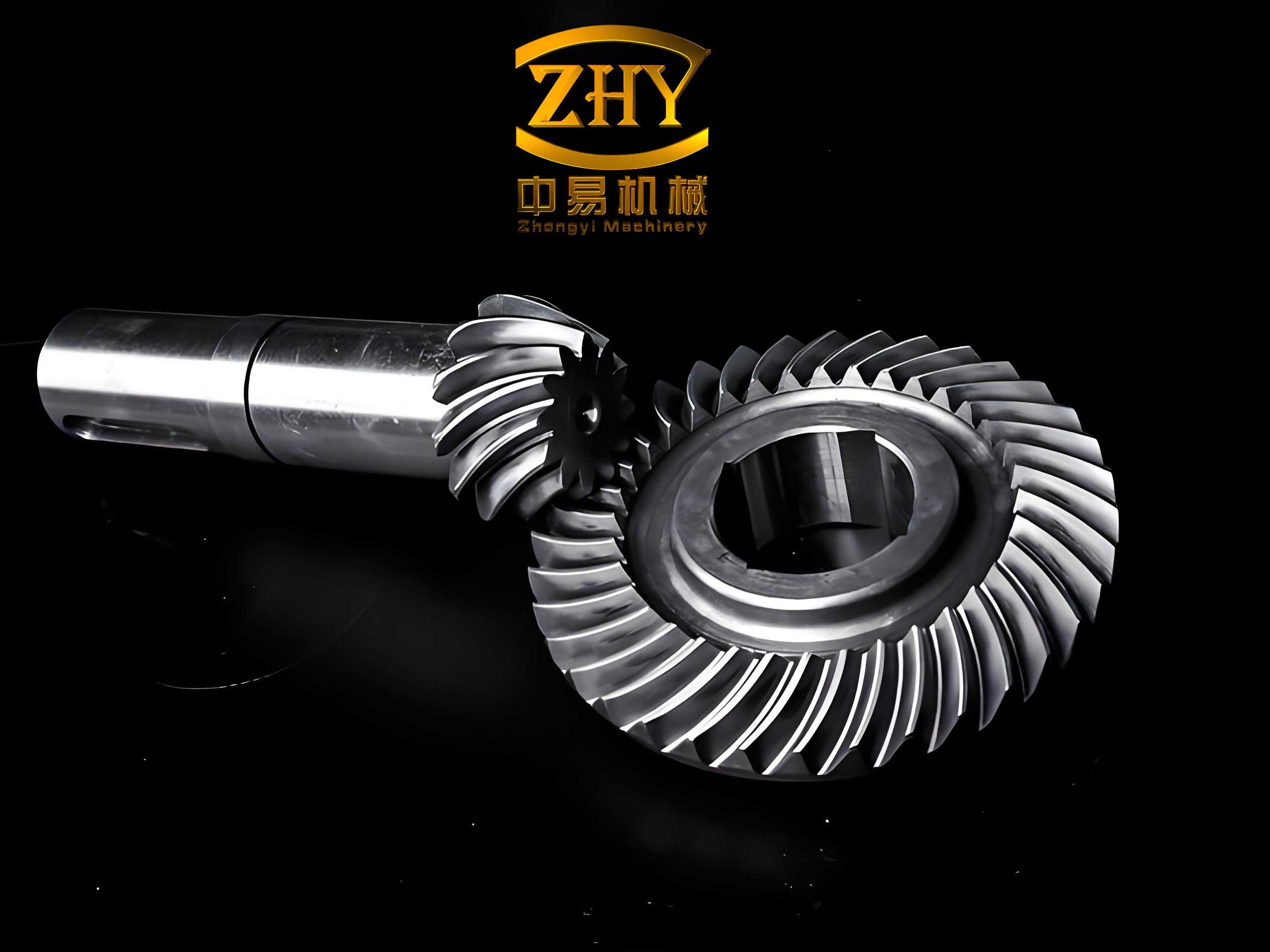
The spread-out helix modified roll method builds upon the foundation of gear engagement theory and differential geometry. Traditional methods, like the ordinary generating process, install the cutter axis perpendicular to the root cone of the gear blank. For a spiral bevel gear pair, this leads to non-parallel cutter axes for the pinion and gear, causing mismatched cutting surfaces and resulting in diagonal contact. In contrast, our proposed approach aligns the cutter axes parallelly by orienting the pinion cutter axis perpendicular to an equidistant surface related to the gear’s root cone, specifically the pinion’s face cone. This alignment ensures that the cutting surfaces of both cutters conform better, promoting proper meshing along the pitch cone direction and theoretically eliminating diagonal contact. The gear is machined using a generating method, while the pinion is processed with a helical modification technique. To achieve a tapered tooth form, the pinion cutter rotates about its axis while simultaneously performing a feed motion along the cradle axis, enabling simultaneous cutting of the tooth flank and root surface. Additionally, this method allows for controllability of the contact pattern by modifying the normal curvatures in both the lengthwise and profile directions. The lengthwise curvature is adjusted through changes in the cutter tip radius, while the profile curvature is modified via variations in the roll ratio, akin to a modified roll technique. Furthermore, the geodesic torsion can be tuned to control the direction of the contact path, provided no curvature interference occurs. This flexibility makes the spread-out helix modified roll method a robust solution for optimizing spiral bevel gear performance.
To mathematically formulate the spread-out helix modified roll method, we establish a kinematic model based on the relative positions and motions among the machine tool, cutter, and workpiece. We employ vector analysis and gear meshing principles, focusing on the midpoint of the tooth surface as the calculation point. The coordinate systems are defined as follows: let Σ0 (O, x, y, z) be the machine coordinate system, with origin fixed at the machine center, xOy representing the machine plane, x-axis horizontal, y-axis vertical, and z-axis perpendicular to the machine plane pointing outward. For the gear, we attach a coordinate system Σ2 (O2, x2, y2, z2), where O2 is the design crossing point, x2-axis aligns with the gear axis, y2-axis coincides with the y-axis, and z2 is determined by the right-hand rule. The cutter axis intersects the machine plane at point Ot. Similarly, for the pinion, we define Σ1 (O1, x1, y1, z1), with O1 as the design crossing point, x1-axis along the pinion axis. The machine adjustment parameters for the gear in generating method include radial setting S2, angular setting q2, machine root angle δf2, axial offset X2, sliding base setting XB2, and roll ratio i02. These parameters are derived from geometric relationships at the calculation point M2 on the gear pitch cone. For instance, the radial setting S2 and angular setting q2 are calculated using the cutter nominal radius r02, spiral angle β, mean cone distance Rm, and root angle θf2. The formulas are:
$$ \tan q_2′ = \frac{r_{02} \cos \beta}{R_m \cos \theta_{f2} – r_{02} \sin \beta} $$
$$ S_2 = \frac{r_{02} \cos \beta}{\sin q_2′} $$
To ensure the actual contact point P2 lies on the x-axis, we adjust the angular setting to:
$$ q_2 = \arcsin \left( \frac{R_{P2} \cos \theta_2}{S_2} \right) $$
where RP2 is the forming radius at point P2, given by RP2 = r02 – W2 – l2 sin α02, with W as the blade edge width, l2 as the cutter cone parameter, and α02 as the pressure angle. For standard tapered teeth, the axial offset X2 is zero, implying XB2 = 0. The roll ratio i02 ensures pure rolling between the generating gear and the workpiece pitch cone, expressed as i02 = cos θf2 / sin δ2, where δ2 is the gear pitch angle. These parameters are summarized in the table below for a typical spiral bevel gear pair.
| Gear Parameter | Pinion | Gear |
|---|---|---|
| Module (mm) | 4.112 | 4 |
| Number of Teeth | 9 | 37 |
| Pressure Angle (°) | 20 | 20 |
| Spiral Angle (°) | 35 | 35 |
| Face Width (mm) | 24 | 24 |
| Pitch Angle (°) | 13.6713 | 76.3287 |
| Face Angle (°) | 17.7987 | 78.2542 |
| Root Angle (°) | 11.7458 | 72.2013 |
| Hand of Spiral | Left | Right |
For the pinion, the spread-out helix modified roll method involves more complex calculations. Based on the indirect generating principle, the pinion tooth surface is considered as the conjugate surface to the gear cutter surface. Thus, we first determine the pinion tooth surface normal vector and curvature parameters at the calculation point P1. Using coordinate transformations, the normal vector n1 in the pinion coordinate system Σ1 is derived from the gear cutter parameters. The transformation matrix from Σ0 to Σ1 is:
$$ \mathbf{M}_{10} = \begin{bmatrix} \cos \delta_{a1} & 0 & -\sin \delta_{a1} \\ 0 & -1 & 0 \\ -\sin \delta_{a1} & 0 & -\cos \delta_{a1} \end{bmatrix} $$
where δa1 is the pinion machine root angle. The components of n1 are:
$$ n_{1x} = \cos \alpha_{02} \cos \delta_{a1} \sin \theta_2 + \sin \alpha_{02} \sin \delta_{a1} $$
$$ n_{1y} = \cos \alpha_{02} \cos \theta_2 $$
$$ n_{1z} = -\cos \alpha_{02} \sin \delta_{a1} \sin \theta_2 + \sin \alpha_{02} \cos \delta_{a1} $$
Here, θ2 is the parameter defining the position on the gear tooth surface. The curvature parameters, including normal curvatures A1′ and B1′ in the lengthwise and profile directions, and geodesic torsion C1′, are calculated using induced curvature formulas. For instance:
$$ \tan \gamma’ = \frac{\cos \alpha_{02} (\tan \alpha_{02} \sin \theta_2 – \tan \theta_{f2})}{\cos \theta_2} $$
$$ \Delta B_1′ = -\frac{\cos \delta_{a1} \cos^2 \theta_2}{R_m \sin \delta_1 \cos \alpha_{02} (\tan \alpha_{02} – \tan \theta_{f2} \sin \theta_2)} $$
where δ1 is the pinion pitch angle. Then, the curvature parameters are:
$$ A_1′ = -\Delta B_1′ \tan^2 \gamma’ – \frac{\cos \alpha_{02}}{R_{P2}} $$
$$ B_1′ = -\Delta B_1′ $$
$$ C_1′ = \Delta B_1′ \tan \gamma’ $$
To achieve a desirable contact pattern, we introduce small modifications ΔA, ΔB, and ΔC to these values, resulting in adjusted curvatures:
$$ A_1 = A_1′ \pm \Delta A $$
$$ B_1 = B_1′ \pm \Delta B $$
$$ C_1 = C_1′ \pm \Delta C $$
Next, we establish the kinematic model for pinion cutting. The pinion cutter generates an Archimedean helicoid due to the helical feed motion, described by the vector equation:
$$ \mathbf{r}_{01} = \begin{bmatrix} S_1 \cos q_1 + R_{P1} \sin \theta_1 \\ -S_1 \sin q_1 + R_{P1} \cos \theta_1 \\ -l_1 \cos \alpha_{01} + p \theta_1 \end{bmatrix} $$
where S1 and q1 are the radial and angular settings for the pinion cutter, RP1 is the forming radius at point P1 (RP1 = r01 + l1 sin α01), r01 is the cutter tip radius, l1 and θ1 are surface parameters, α01 is the pinion pressure angle, and p is the helical feed parameter. The normal vector to this surface is:
$$ \mathbf{n}_{01} = \frac{1}{\sqrt{R_{P1}^2 + (p \sin \alpha_{01})^2}} \begin{bmatrix} R_{P1} \cos \alpha_{01} \sin \theta_1 – p \sin \alpha_{01} \cos \theta_1 \\ R_{P1} \cos \alpha_{01} \cos \theta_1 + p \sin \alpha_{01} \sin \theta_1 \\ R_{P1} \sin \alpha_{01} \end{bmatrix} $$
The pinion tooth surface is the envelope of this cutter surface relative to the pinion motion. The relative velocity between the cutter and pinion is crucial for the meshing condition. The position vector of the pinion design crossing point O1 is:
$$ \mathbf{r} = \begin{bmatrix} X_1 \cos \delta_{a1} \\ 0 \\ X_1 \sin \delta_{a1} + X_{B1} \end{bmatrix} $$
where X1 is the axial offset and XB1 is the sliding base setting for the pinion. The angular velocity of the cutter is ω0 = z (unit vector along z-axis), and the pinion angular velocity is ω1 = i01 x1, with i01 as the roll ratio. The relative angular velocity ω01 and relative velocity v01 are:
$$ \boldsymbol{\omega}_{01} = \boldsymbol{\omega}_0 – \boldsymbol{\omega}_1 = \mathbf{z} – i_{01} \mathbf{x}_1 $$
$$ \mathbf{v}_{01} = \boldsymbol{\omega}_{01} \times \mathbf{r}_{01} – \boldsymbol{\omega}_1 \times \mathbf{r} $$
The coordinate transformation from Σ1 to Σ0 involves rotations by δa1 and φ (cradle rotation angle), given by:
$$ \mathbf{M}_{01} = \begin{bmatrix} \cos \delta_{a1} & \sin \delta_{a1} \sin \varphi & -\sin \delta_{a1} \cos \varphi \\ 0 & \cos \varphi & \sin \varphi \\ \sin \delta_{a1} & -\cos \delta_{a1} \sin \varphi & \cos \delta_{a1} \cos \varphi \end{bmatrix} $$
The gear meshing equation and surface compatibility conditions yield a system of equations:
$$ \mathbf{r}_{01} = \mathbf{M}_{01} \mathbf{r}_{p1} + \mathbf{r} $$
$$ \mathbf{n}_{01} = \mathbf{M}_{01} \mathbf{n}_1 $$
$$ \mathbf{v}_{01} \cdot \mathbf{n}_{01} = 0 $$
where rp1 = [Rm cos δ1, 0, -Rm sin δ1]^T is the position vector of point P1 in Σ1. Additionally, the curvature conditions provide:
$$ k_1 = \frac{A_1 B_1 – C_1^2}{B_1} $$
$$ \frac{C_1}{B_1} = \frac{\boldsymbol{\omega}_{01} \cdot \mathbf{e}_2}{\boldsymbol{\omega}_{01} \cdot \mathbf{e}_1} $$
$$ \frac{1}{B_1} = -\frac{(2c) \mathbf{v}_0 \cdot \mathbf{n}_{01} + (\boldsymbol{\omega}_{01}, \mathbf{v}_0, \mathbf{n}_{01})}{(\boldsymbol{\omega}_{01} \cdot \mathbf{e}_1)^2} $$
Here, k1 is the normal curvature of the cutter surface in the lengthwise direction, e1 and e2 are direction vectors along the cutter’s lengthwise and profile directions, v0 is the cutter velocity vector, and 2c is the second-order modified roll coefficient. This system comprises nine independent scalar equations with nine unknowns: S1, q1, r01, θ1, l1, X1, XB1, i01, and 2c. We solve these nonlinear equations using numerical methods like the fsolve function in MATLAB, with a tolerance of 10^-4. The results for a sample spiral bevel gear pair are summarized in the table below.
| Adjustment Parameter | Pinion Concave Side | Gear Convex Side |
|---|---|---|
| Cutter Diameter (mm) | 157.1152 | 150.7729 |
| Radial Setting (mm) | 67.9110 | 66.3235 |
| Angular Setting (°) | 71.5114 | 67.4435 |
| Axial Offset (mm) | 1.9726 | 0 |
| Sliding Base Setting (mm) | -7.6148 | 0 |
| Machine Root Angle (°) | 17.7987 | 72.2013 |
| Roll Ratio | 4.3399 | 1.0265 |
| Second-Order Modified Roll Coefficient | 0.0126 | 0 |
| Helical Feed Parameter (mm/rad) | 7.8975 | 0 |
With these parameters, we proceed to simulation analysis to validate the spread-out helix modified roll method for spiral bevel gears. We use Creo software for virtual machining, which involves creating parametric 3D models of the gear blanks and cutters based on the geometric parameters. The cutting process is discretized into small steps, each representing a momentary position of the cutter. Through Boolean subtraction operations between the blank solid and a series of cutter solids, we simulate the milling process. This approach effectively replicates the actual cutting action, as the cutter envelope forms the desired tooth surface. After machining, the tooth surface is reconstructed from key points to ensure smoothness, resulting in accurate 3D models of the spiral bevel gear pair. These models are then assembled in the software with appropriate connections, such as pin joints, to form a gear pair. A gear pair connection is established in the mechanism module, and a driving torque is applied to the pinion for kinematic analysis. Dynamic interference detection during simulation reveals the instantaneous contact pattern, typically displayed as red curves on the tooth surface. For our spiral bevel gear pair, the contact pattern appears elliptical and slightly inclined relative to the root cone line, indicating improved contact characteristics compared to traditional methods.
To further verify the effectiveness of the spread-out helix modified roll method, we perform tooth contact analysis (TCA) and compare it with results from the Gleason SGM method. TCA involves calculating the contact points under load by solving the equations of meshing and surface tangency. For our gear pair, the TCA results show that the contact path on the gear convex surface is nearly perpendicular to the root cone line, demonstrating the elimination of diagonal contact. In contrast, the Gleason SGM method often produces a diagonal contact pattern due to the inherent pressure angle errors. This comparison underscores the advantage of our method in achieving a more favorable contact pattern for spiral bevel gears. The ability to control curvatures through ΔA, ΔB, and ΔC adjustments allows for fine-tuning the contact zone size and location, enhancing the gear’s load-carrying capacity and noise performance. Moreover, the simulation confirms that the spread-out helix modified roll method can be implemented efficiently in CNC gear milling machines, reducing the need for repetitive trial-and-error adjustments during manufacturing.
Following the simulation, we conduct experimental cutting on a CNC gear milling machine using the calculated parameters for the spiral bevel gear pair. The gear blanks are mounted according to the specified machine settings, and the cutting process is carried out with high precision. After machining, the gear pair is installed on a rolling tester with the prescribed mounting distances to check the tooth contact pattern under light load. The observed contact pattern on the gear convex surface aligns closely with the TCA predictions, showing an elliptical shape with minimal diagonal tendency. Minor discrepancies may arise due to manufacturing errors, such as cutter wear or machine tool inaccuracies, but overall, the results validate the theoretical framework. This experimental confirmation highlights the practicality of the spread-out helix modified roll method for industrial applications, where consistent and high-quality spiral bevel gears are essential. By eliminating diagonal contact, this method contributes to longer gear life, reduced maintenance costs, and improved system reliability in critical applications like aerospace transmissions.
In conclusion, the spread-out helix modified roll method offers a robust solution to the diagonal contact problem in spiral bevel gears. Through detailed mathematical modeling based on differential geometry and gear meshing theory, we derive the machine adjustment parameters for both gear and pinion. The simulation analysis using 3D virtual machining and tooth contact analysis demonstrates the method’s capability to produce a favorable contact pattern, effectively eliminating diagonal contact. Experimental cutting and rolling tests further corroborate these findings, showing good agreement between theory and practice. This method not only enhances the meshing performance of spiral bevel gears but also streamlines the manufacturing process by reducing the need for iterative adjustments. Future work could explore optimization algorithms for the curvature modifications or extend the method to other gear types, such as hypoid gears. Overall, the spread-out helix modified roll method represents a significant advancement in spiral bevel gear technology, promising higher efficiency and reliability in motion transmission systems.
The development of advanced manufacturing techniques for spiral bevel gears is crucial for modern engineering applications. As demands for higher power density and quieter operation increase, methods like the spread-out helix modified roll become increasingly valuable. By integrating theoretical analysis with practical implementation, we can continue to improve the design and production of spiral bevel gears, ensuring they meet the rigorous standards of industries such as automotive, aviation, and robotics. The use of simulation tools and CNC technology further accelerates this progress, enabling rapid prototyping and customization. In essence, the spread-out helix modified roll method exemplifies how innovative approaches can address long-standing challenges in gear manufacturing, paving the way for more efficient and durable mechanical systems.