
In the field of mechanical engineering dynamics, the analysis of vibrational characteristics forms a cornerstone for ensuring the reliability and performance of power transmission systems. A fundamental approach involves decoupling the system of vibration differential equations for linear time-invariant systems. This is achieved by substituting physical coordinates with modal coordinates. This transformation, facilitated by the modal matrix whose columns represent the mode shapes, yields a set of independent equations described by modal coordinates and parameters. Solving this decoupled system provides the essential modal parameters of the system. The modal parameters extracted through analytical or numerical means, such as via Finite Element Analysis (FEA) software, serve as a critical foundation for subsequent stages. These parameters enable detailed vibration characteristic analysis, guide structural optimization design processes, and support diagnostic efforts to understand and mitigate system vibrations.
The widespread adoption of spiral bevel gear sets in demanding applications within aerospace, automotive, and heavy engineering machinery has underscored the critical importance of incorporating dynamic analysis early in the design phase. Predicting the dynamic behavior of spiral bevel gears has thus attracted significant attention. Among the key dynamic characteristics are the inherent properties of the vibrational system, primarily including natural frequencies and their associated mode shapes. These inherent properties profoundly influence the system’s dynamic response, the generation and transmission of dynamic loads, and the very nature of the vibration patterns. Consequently, performing a simulation-based analysis of these inherent properties using Finite Element Analysis during the design process is not merely beneficial but essential for robust design.
This work details a methodology for the dynamic characterization of a spiral bevel gear. The process begins with the parametric creation of a three-dimensional model using CAD software, which is then seamlessly imported into a dedicated finite element pre-processor. Utilizing a powerful solver, a modal analysis is conducted on the spiral bevel gear model. This analysis yields the lower-order natural frequencies and their corresponding dominant mode shapes, providing valuable insights into the dynamic characteristics of the spiral bevel gear and forming a basis for avoiding resonant conditions in operation.
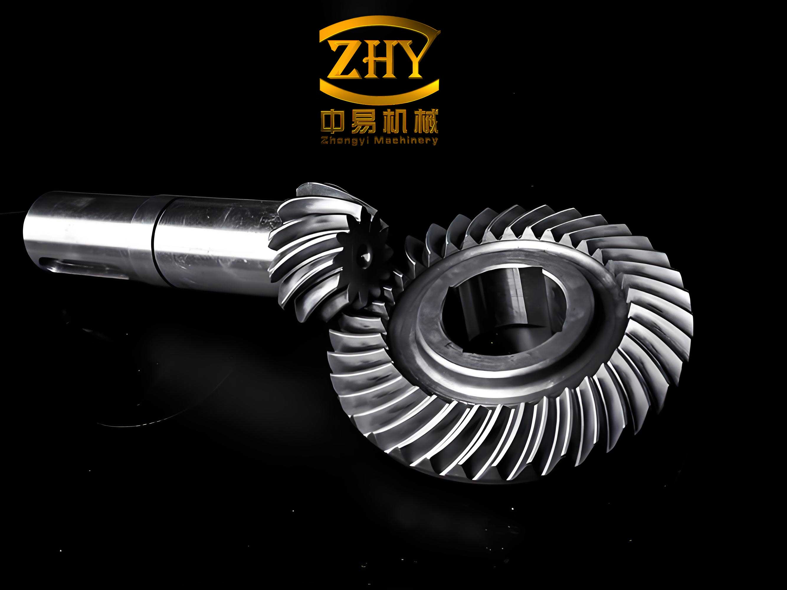
Parametric Modeling of Spiral Bevel Gears
The accuracy of any finite element analysis is intrinsically linked to the fidelity of the geometric model. For complex components like spiral bevel gears, a parametric modeling approach is highly advantageous. It allows for easy modification of key design parameters (e.g., number of teeth, module, spiral angle) and regeneration of an accurate geometry without rebuilding the model from scratch. The fundamental dimensions for the spiral bevel gear analyzed in this study are defined parametrically, as summarized in the table below.
| Parameter | Symbol | Value | Unit |
|---|---|---|---|
| Number of Teeth | Z | 40 | – |
| Module | m | 3 | mm |
| Spiral Angle | β | 35 | ° |
| Pressure Angle | α | 20 | ° |
| Shaft Angle | Σ | 90 | ° |
| Face Width | B | 20 | mm |
| Cutter Diameter | D | 150 | mm |
| Hand of Spiral | – | Right | – |
The tooth profile of a spiral bevel gear is based on a spherical involute. Modern CAD software provides tools to define complex curves using parametric equations. Utilizing the software’s programmable feature, the tooth flank geometry can be constructed by defining the spherical involute profile in terms of spherical coordinates. The governing equations for the spherical involute form the core of this parametric sketch, which is then swept along a prescribed spiral path to generate the solid tooth form. The complete, fully parametric three-dimensional model of the spiral bevel gear is generated by patterning this single tooth geometry around the gear axis. This parametric model ensures geometric accuracy and facilitates design iterations.
Theoretical Foundation of Finite Element Modal Analysis
Modal analysis is a fundamental technique in structural dynamics used to determine the inherent vibration characteristics of a component or assembly. These characteristics, the natural frequencies and mode shapes, are intrinsic properties determined by the structure’s mass distribution, stiffness, and damping (though often neglected for free vibration). Starting from the principles of elastic mechanics and applying the Finite Element Method (FEM), the dynamic behavior of a structure like a spiral bevel gear can be described by a system of differential equations.
The general equation of motion for a multi-degree-of-freedom system is given by:
$$ [M]\{\ddot{x}\} + [C]\{\dot{x}\} + [K]\{x\} = \{F(t)\} $$
where:
$[M]$ is the global mass matrix,
$[C]$ is the global damping matrix,
$[K]$ is the global stiffness matrix,
$\{F(t)\}$ is the time-varying force vector,
$\{\ddot{x}\}$, $\{\dot{x}\}$, and $\{x\}$ are the acceleration, velocity, and displacement vectors, respectively.
For the specific case of free vibration analysis, where external forces are absent ($\{F(t)\} = \{0\}$), and assuming light damping that can be neglected for determining natural frequencies, the equation simplifies to the undamped free vibration equation:
$$ [M]\{\ddot{x}\} + [K]\{x\} = \{0\} $$
Assuming a harmonic solution for free vibration of the form $\{x\} = \{\phi\} e^{i \omega t}$, where $\{\phi\}$ is the mode shape vector and $\omega$ is the circular frequency, and substituting into the undamped equation, we arrive at the classic eigenvalue problem:
$$ \left( [K] – \omega^2 [M] \right) \{\phi\} = \{0\} $$
For a non-trivial solution ($\{\phi\} \neq \{0\}$), the determinant must be zero:
$$ \det\left( [K] – \omega^2 [M] \right) = 0 $$
Solving this eigenvalue problem yields ‘n’ eigenvalues, $\omega_i^2$ (where $i = 1, 2, 3, …, n$), and their corresponding eigenvectors, $\{\phi_i\}$. The natural frequency $f_i$ (in Hz) is related to the circular frequency $\omega_i$ (in rad/s) by $f_i = \omega_i / (2\pi)$. The eigenvector $\{\phi_i\}$ describes the deformed shape of the structure when vibrating at the frequency $f_i$, known as the i-th mode shape.
Modal analysis, therefore, involves the numerical solution of this eigenvalue problem for the finite element model of the spiral bevel gear. The results, including modal participation factors which indicate the contribution of each mode to the response in a specific direction, are crucial for understanding the dynamic behavior of the spiral bevel gear.
Finite Element Modeling and Modal Solution for Spiral Bevel Gears
Geometry Import and Mesh Generation
Efficient integration between CAD and CAE tools is vital for modern simulation workflows. Advanced pre-processors employ technologies like Direct Geometry Access (DGA) to read native CAD geometry directly. This eliminates the error-prone and time-consuming process of recreating geometry within the FEA environment, ensuring that the analyzed model is an exact digital twin of the designed spiral bevel gear. The parametrically generated three-dimensional model of the spiral bevel gear is imported directly into the pre-processor using this seamless interface.
Following geometry import, the model is discretized into finite elements. For the complex, curved geometry of a spiral bevel gear, tetrahedral elements are often suitable. In this analysis, a second-order tetrahedral element with 10 nodes (TET10) is selected. This element type provides better accuracy in modeling curved boundaries compared to its first-order counterpart. An automatic meshing algorithm is employed, with global and local size controls to ensure a sufficiently refined mesh, particularly in regions of geometric complexity like the tooth root fillets and active flanks, where stress concentrations and detailed modal behavior are expected. The meshed model of the spiral bevel gear forms the basis for all subsequent computations.
Material Properties and Boundary Conditions
The material assigned to the spiral bevel gear model significantly influences its dynamic properties. The gear is modeled using standard alloy steel (e.g., AISI 1045 or equivalent 45# steel). The material properties defined for the linear-elastic analysis are:
- Young’s Modulus (Elastic Modulus), $E = 2.1 \times 10^5 \text{ MPa}$
- Poisson’s Ratio, $\nu = 0.3$
- Density, $\rho = 7.8 \times 10^{-9} \text{ T/mm}^3$ (or $7800 \text{ kg/m}^3$)
These properties are assigned to the entire volume of the meshed spiral bevel gear.
Boundary conditions must be applied to simulate the physical mounting of the gear. In a typical transmission, the spiral bevel gear is mounted on a shaft via an interference fit or keyed connection. For a modal analysis, which determines free-vibration characteristics, only constraints that eliminate rigid body modes are necessary, as natural frequencies are independent of applied loads. To simulate the connection to the shaft, all degrees of freedom (translational and rotational) on the inner cylindrical surface of the gear bore are constrained, except for the rotation about the gear’s own axis. This condition restricts five degrees of freedom, allowing only rotation about the gear axis, which is a reasonable approximation for a free vibration analysis where the gear is considered fixed to a rigid shaft for support. This setup prevents the six rigid body modes (three translations and three rotations) and allows the solver to extract only the flexible body modes of the spiral bevel gear.
Solution and Post-Processing
The modal analysis is performed using a dedicated solver (e.g., NASTRAN) configured for real eigenvalue extraction. The Lanczos or Block Lanczos method is typically chosen for its efficiency in extracting a subset of eigenvalues from large, sparse matrices. The analysis is set to extract the first 10 modes of the spiral bevel gear. The solver computes the eigenvalues ($\omega_i^2$) and eigenvectors ($\{\phi_i\}$) from the global mass and stiffness matrices assembled from the finite element model.
Post-processing involves reviewing and animating the results. The primary outputs are the natural frequencies and their associated mode shapes for the spiral bevel gear. The frequencies are tabulated, and each mode shape is visualized as an animated deformation plot, showing the relative displacement of all nodes on the gear when vibrating at that specific natural frequency. This visual representation is key to identifying the type of vibration (e.g., bending, torsion, umbrella modes) and locating areas of maximum displacement or strain.
Results and Discussion of Spiral Bevel Gear Modal Analysis
The finite element modal analysis successfully extracted the first ten natural frequencies of the constrained spiral bevel gear model. These frequencies are listed in the table below. It is a well-established principle in structural dynamics that lower-order modes generally have a more significant influence on the dynamic response of a structure under broad-band or low-frequency excitation, making their identification critically important for the spiral bevel gear.
| Mode Number (i) | Natural Frequency, $f_i$ (Hz) | Primary Mode Shape Description |
|---|---|---|
| 1 | 6831.2 | Circumferential Bending (1st Nodal Diameter) |
| 2 | 6877.1 | Circumferential Bending (1st Nodal Diameter, orthogonal to Mode 1) |
| 3 | 12075 | Circumferential Bending (2nd Nodal Diameter) |
| 4 | 12087 | Circumferential Bending (2nd Nodal Diameter, orthogonal to Mode 3) |
| 5 | 12584 | Umbrella Mode (Axial/Circumferential) |
| 6 | 25022 | Torsional Vibration |
| 7 | 25093 | Combined Bending/Torsion |
| 8 | 30798 | Higher Order Circumferential Bending |
| 9 | 30987 | Higher Order Circumferential Bending |
| 10 | 72685 | Complex Localized Tooth Mode |
Analysis of Lower-Order Mode Shapes
The visualization of the mode shapes reveals distinct patterns of deformation for the spiral bevel gear:
- Modes 1 & 2 (~6830-6880 Hz): These are the first pair of flexible modes, closely spaced in frequency. They represent the first nodal diameter bending modes of the gear blank. The deformation pattern shows the gear rim bending in a sinusoidal pattern around the circumference, with one diameter remaining stationary (the nodal diameter). Mode 1 and Mode 2 are identical in form but oriented 90 degrees apart, a typical characteristic for axisymmetric structures with slight asymmetries introduced by the spiral teeth or the finite element mesh.
- Modes 3 & 4 (~12075-12087 Hz): This pair constitutes the second nodal diameter bending modes. The deformation pattern has two nodal diameters, creating a more complex circumferential bending shape. Again, the two modes in the pair are degenerate (same frequency) with orthogonal orientations.
- Mode 5 (~12584 Hz): This mode is characterized by an “umbrella” or “breathing” type deformation. The gear rim moves primarily in an axial direction relative to the constrained bore, accompanied by radial expansion/contraction. This mode significantly affects the mesh stiffness and load distribution along the face width of the spiral bevel gear.
- Mode 6 (~25022 Hz): This is identified as a predominantly torsional mode. The primary deformation involves twisting of the gear blank about its axis, with the teeth on one side lagging those on the opposite side. Torsional modes are critical as they directly relate to the transmission of oscillatory torque.
The analysis of these mode shapes indicates that circumferential bending and torsional vibrations are the dominant modal families for this spiral bevel gear in its lower-frequency range. The umbrella mode also presents a significant deformation pattern. Understanding which operational excitations (e.g., tooth meshing frequency, sideband frequencies, shaft rotational frequencies) coincide with these natural frequencies is paramount. Resonance occurs when an excitation frequency matches or is close to a natural frequency, leading to dramatically amplified vibrations, increased noise, and accelerated fatigue failure.
Implications for Design and Avoidance of Resonance
The primary practical application of a modal analysis for a spiral bevel gear is to avoid resonant conditions during operation. The designer must ensure that the predicted natural frequencies, especially the fundamental ones (Modes 1-6), are sufficiently separated from major excitation sources. The most common and powerful excitation in gearing is the Tooth Meshing Frequency (TMF) and its harmonics. The TMF is calculated as:
$$ \text{TMF} = N \times \text{RPM} / 60 $$
where $N$ is the number of teeth on the gear and RPM is its rotational speed in revolutions per minute.
For the example spiral bevel gear with 40 teeth, the TMF equals the gear speed in Hz multiplied by 40. To avoid resonance, a safe margin (e.g., 15-20%) should be maintained between the TMF (and its 2x, 3x harmonics) and any identified natural frequency. The results from Table 2 allow the designer to establish “critical speed” ranges for the input or output shafts connected to the spiral bevel gear. For instance, if the gear’s operational speed range would cause the TMF to fall near 6830 Hz or 12584 Hz, the design may need modification.
If a potential resonance is identified, the design of the spiral bevel gear can be modified parametrically to shift its natural frequencies. This is where the initial parametric modeling proves its value. Changes can be made to:
1. Mass Distribution: Modifying the web design, adding lightening holes, or changing the rim thickness alters the mass matrix $[M]$.
2. Stiffness Distribution: Increasing the gear blank stiffness, optimizing the web structure, or using a material with a higher Young’s Modulus $E$ affects the stiffness matrix $[K]$.
3. Material: Switching to a material with a different density and modulus will shift all frequencies. The natural frequency scales with $\sqrt{E/\rho}$.
A quick parametric study can be conducted by updating the CAD model and re-running the modal analysis to verify the frequency shift, helping to tune the dynamic response of the spiral bevel gear system effectively.
Extended Analysis: Parametric Influence on Modal Properties
To further generalize the findings and provide deeper insight, a brief parametric study illustrates how key design variables of a spiral bevel gear influence its modal properties. While the core analysis focused on one specific geometry, understanding trends is crucial for designers.
Consider the simplified relationship for the fundamental bending frequency of a ring, which shares characteristics with a gear blank. The natural frequency for a thin ring in a particular bending mode is proportional to:
$$ f_n \propto \frac{1}{R^2} \sqrt{\frac{E I}{\rho A}} $$
where $R$ is the mean radius, $E$ is Young’s modulus, $I$ is the area moment of inertia of the cross-section, $\rho$ is density, and $A$ is the cross-sectional area. Although a spiral bevel gear is more complex, similar trends hold.
The table below summarizes the qualitative effect of changing major spiral bevel gear parameters on its natural frequencies, based on engineering mechanics principles and FEA results from various studies.
| Design Parameter | Change | Effect on Stiffness (K) | Effect on Mass (M) | Net Effect on Natural Frequencies (f) | Primary Mode Affected |
|---|---|---|---|---|---|
| Face Width (B) | Increase | Increases (∝ B^3 for bending) | Increases (∝ B) | Increases (Stiffness dominates) | Bending, Torsion |
| Rim Thickness | Increase | Increases significantly | Increases | Increases | Bending, Umbrella |
| Web Thickness/Design | Increase/Add ribs | Increases | Slight increase | Increases | All, especially umbrella |
| Number of Teeth (Z) for fixed Pitch Diameter | Increase | Tooth bending stiffness may decrease slightly; Blank stiffness unchanged. | Unchanged | Minor decrease or no change in blank modes; Tooth modes lower. | Tooth bending modes |
| Spiral Angle (β) | Increase | Changes load distribution; may slightly alter effective torsional stiffness. | Negligible | Minor shifts, not primary driver. | Mixed modes |
| Material (E, ρ) | Higher E (e.g., Steel to Ti-Alloy) | Increases (∝ E) | Decreases (ρ lower for Ti) | Significant Increase (f ∝ √(E/ρ)) | All modes |
| Material (E, ρ) | Higher ρ (e.g., Steel to Tungsten) | Increases (E higher for W) | Increases greatly | Decrease (Mass effect dominates) | All modes |
This parametric understanding allows a designer to make informed decisions. For example, if the fundamental bending frequency of a spiral bevel gear is too low and risks resonance, increasing the face width or adding a stiffer web design would be effective countermeasures, rather than simply adding mass everywhere.
Conclusion
The integration of parametric three-dimensional modeling and advanced finite element analysis provides a powerful and necessary framework for the dynamic design evaluation of spiral bevel gears. This work has detailed a complete methodology, from the parametric generation of an accurate geometric model based on spherical involute theory to the performance of a detailed modal analysis using industry-standard FEA techniques. The procedure successfully extracted the first ten natural frequencies and corresponding mode shapes for a representative spiral bevel gear.
The results conclusively demonstrate that the lower-order modes, particularly circumferential bending (nodal diameter) modes, umbrella modes, and torsional modes, are the most critical for the dynamic behavior of the spiral bevel gear. These modes represent the most likely paths to resonant excitation during operation. The primary value of this analysis lies in its predictive capability. By comparing the calculated natural frequencies with the expected excitation spectrum (dominated by the tooth meshing frequency and its harmonics), designers can proactively identify and avoid critical speed ranges. This enables the design of spiral bevel gear transmission systems that are not only structurally sound but also dynamically quiet, reliable, and durable.
Furthermore, the parametric nature of the underlying CAD model facilitates rapid design iteration and optimization. If a potential resonance is predicted, key geometric parameters can be adjusted efficiently, and a new modal analysis can be performed to verify the shift in natural frequencies. This closed-loop simulation-driven design process is essential for developing high-performance spiral bevel gears for the demanding applications found in aerospace, robotics, and advanced vehicular systems, ensuring their operational success and longevity.