
In my extensive experience as a mechanical engineer specializing in textile equipment, I have encountered numerous challenges related to the durability and performance of critical components. One persistent issue that has demanded attention is the frequent failure of the spiral gear shaft in certain types of carding and lap forming machines. The spiral gear is a fundamental part of the transmission system that drives the lower fluted roller, and its malfunction can lead to significant downtime, reduced product quality, and increased maintenance costs. This article details my first-hand account of analyzing the root causes of these failures and implementing a robust, cost-effective modification that has proven successful in industrial applications. Throughout this discussion, I will emphasize the central role of the spiral gear and its shaft, exploring the mechanical principles, material science, and practical engineering solutions involved.
The specific machine in question is a model analogous to the single-beater lap former. In its original configuration, the spiral gear shaft, which transmits motion from the upper to the lower mechanism, was integrally cast with its supporting bracket and adjustment nut. This design resulted in a cantilevered structure where the spiral gear shaft was subjected to substantial bending moments. The spiral gear itself, with its helical teeth designed for smooth torque transmission, imposes combined loads of torsion and bending on the shaft. The inherent weakness of the cast material at the shaft shoulder, a stress concentration point, made it prone to fracture. The failure of this spiral gear assembly would halt production, and repairing the monolithic cast piece was often impractical, leading to costly replacements.
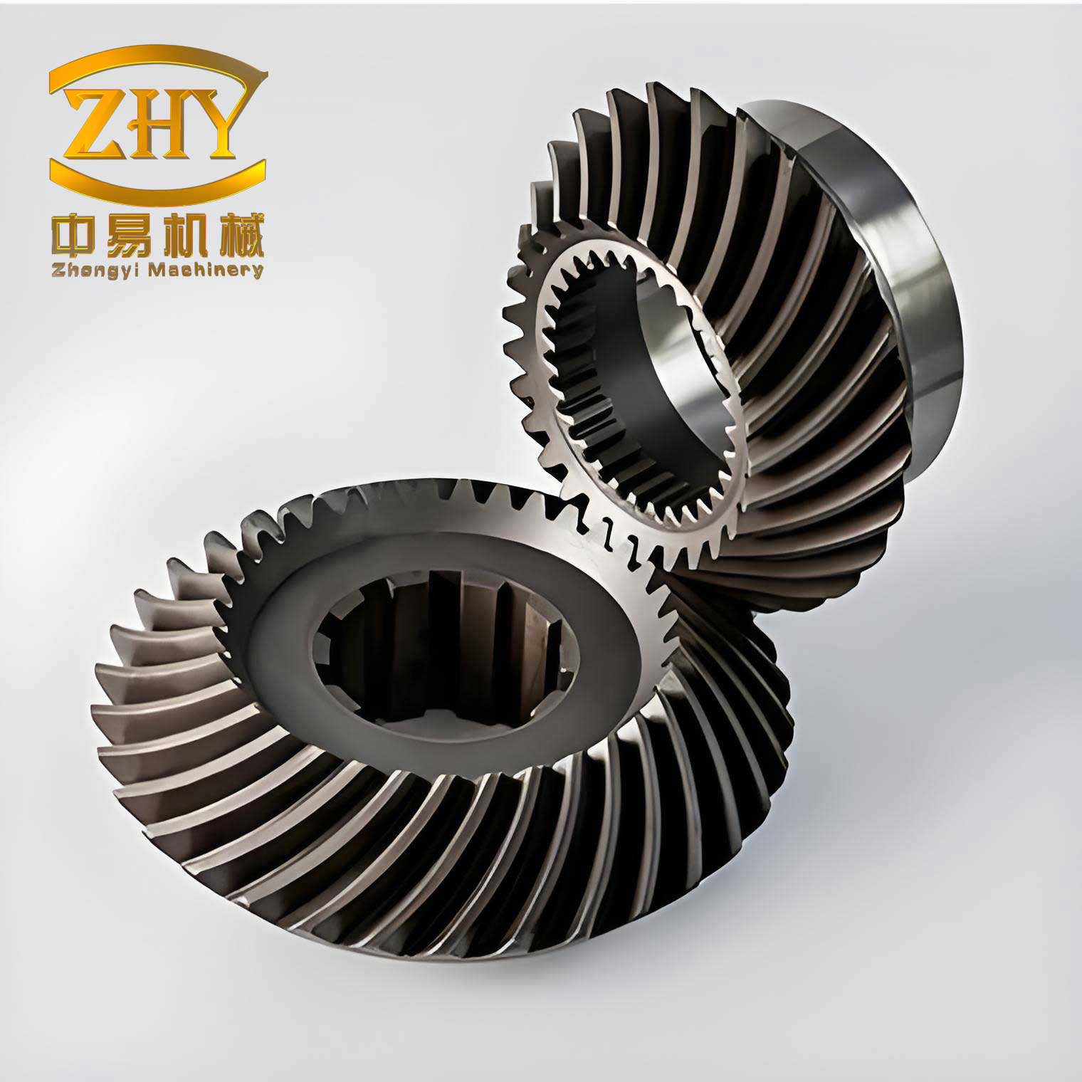
To understand the failure mechanism, a thorough stress analysis of the spiral gear shaft is essential. The primary mode of failure is fatigue fracture due to cyclic bending stress. The bending stress ($\sigma_b$) at the critical section (the shaft shoulder) can be expressed by the classic formula for a cantilever beam with a concentrated load:
$$\sigma_b = \frac{M y}{I}$$
where $M$ is the bending moment, $y$ is the distance from the neutral axis to the outer fiber, and $I$ is the area moment of inertia. For a solid circular shaft of diameter $d$, $I = \frac{\pi d^4}{64}$ and $y = d/2$. The bending moment $M$ is generated by the tangential force ($F_t$) from the spiral gear meshing. The force on the spiral gear teeth can be derived from the transmitted torque ($T$):
$$F_t = \frac{2T}{d_p}$$
where $d_p$ is the pitch diameter of the spiral gear. The bending moment at the shoulder, located a distance $L$ from the force application point, is $M = F_t \cdot L$. Combining these, the maximum bending stress becomes:
$$\sigma_{b,max} = \frac{32 F_t L}{\pi d^3} = \frac{64 T L}{\pi d^3 d_p}$$
This equation highlights the inverse cubic relationship between shaft diameter and stress. The original cast shaft likely had a diameter that was marginally sufficient, but the cast material’s lower fatigue strength and the stress concentration factor ($K_t$) at the sharp shoulder fillet (if poorly designed) drastically reduced its effective strength. The stress concentration factor modifies the nominal stress:
$$\sigma_{max} = K_t \cdot \sigma_{nom}$$
For a shaft with a shoulder fillet, $K_t$ can be quite high, often between 1.5 and 3, depending on the fillet radius ratio. The cast material, typically a gray iron or low-grade steel, has a tensile strength ($S_{ut}$) and endurance limit ($S_e$) far below that of forged or machined steel. The modified endurance limit ($S_e’$) for the component is:
$$S_e’ = k_a k_b k_c k_d k_e k_f S_e$$
where $k_a$ is the surface finish factor, $k_b$ the size factor, $k_c$ the load factor, $k_d$ the temperature factor, $k_e$ the reliability factor, and $k_f$ the miscellaneous effects factor (including stress concentration). For a cast surface under bending, $k_a$ is low, and with a significant stress concentration ($k_f = 1/K_t$), the effective $S_e’$ can be a small fraction of the base material’s endurance limit. When the cyclic stress $\sigma_a$ exceeds $S_e’$, fatigue failure ensues after a certain number of cycles ($N_f$), predicted by models like the Basquin equation:
$$\sigma_a = \sigma_f’ (2N_f)^b$$
where $\sigma_f’$ is the fatigue strength coefficient and $b$ the fatigue strength exponent. The following table summarizes key material properties and stress factors relevant to the original and modified spiral gear shaft designs:
| Parameter | Original Cast Shaft | Modified Steel Shaft |
|---|---|---|
| Material | Cast Iron / Low-Carbon Steel | AISI 1045 Steel (Medium Carbon) |
| Tensile Strength, $S_{ut}$ (MPa) | ~250-400 | ~585 |
| Yield Strength, $S_{y}$ (MPa) | ~150-250 | ~450 |
| Endurance Limit, $S_e$ (estimated, MPa) | ~100-150 | ~240-280 |
| Surface Finish Factor, $k_a$ | 0.7 (as-cast) | 0.9 (machined) |
| Size Factor, $k_b$ | ~0.9 | ~0.9 |
| Stress Concentration Factor, $K_t$ | High (~2.5) | Low (~1.2, with generous fillet) |
| Effective Endurance Limit, $S_e’$ (MPa) | ~30-60 | ~180-220 |
The analysis clearly indicated that the original spiral gear shaft was operating in a regime where the alternating stress approached or exceeded its greatly reduced endurance limit. This justified the frequent fractures observed at the shoulder. My initial attempt at a fix involved manufacturing a new short shaft from AISI 1045 steel and attempting to join it to the existing bracket using an interference fit supplemented with adhesive. This approach addressed the material weakness but not the structural weakness of the bracket’s thin wall around the shaft seat. The stress in the bracket material itself led to cracking and failure after a few months. This reinforced the need for a holistic redesign that considered the entire spiral gear shaft assembly, not just the shaft itself.
The successful modification, which I designed and implemented, adopts a three-piece assembled configuration. This approach decouples the functions of support, force transmission, and adjustment, allowing each part to be optimized for its specific role. The core of the assembly remains the original supporting bracket, but it is modified by machining a precise cylindrical bore through it. This bracket acts as the housing. The new spiral gear shaft is a separate component machined from AISI 1045 steel (equivalent to Chinese grade 45 steel). This material offers an excellent balance of strength, toughness, and machinability, making it ideal for the dynamic loads imparted by the spiral gear. The shaft is designed with a generous fillet at the shoulder to minimize stress concentration. The third piece is a new adjustment nut, machined from AISI 1020 steel (a mild steel), which threads onto the end of the shaft to secure the axial position and preload the assembly.
The critical dimensions and tolerances are carefully specified. The shaft’s diameter for the section fitting into the bracket bore is given a slight interference fit, specifically a m6 or n6 tolerance class relative to an H7 hole in the bracket, ensuring a secure press fit without requiring adhesive. The length of this press-fit section is deliberately made slightly shorter than the thickness of the bracket, ensuring that the full clamping force from the nut acts on the shaft’s end face and not on the press-fit interface, preventing the bracket from splitting. The shaft features a machined flat or a hex section for the nut, and the overall length is calibrated so that when assembled, the spiral gear is correctly positioned relative to its mating gear. The assembly process is straightforward: the steel spiral gear shaft is pressed into the modified bracket, the spiral gear is keyed onto the shaft, and the adjustment nut is tightened to the specified torque, locking the entire assembly. This design transforms the weak cantilever into a much more rigid and supported structure. The bending moment arm is effectively reduced, and the stress is now borne by the high-strength steel shaft with a favorable stress profile.
The performance of this modified spiral gear shaft assembly was rigorously tested. We conducted comparative trials on multiple machines, monitoring parameters like vibration, noise, temperature, and, most importantly, the quality of the output lap. The lap uniformity, a critical metric in textile processing, showed marked improvement. The following table presents a summary of lap uniformity test results before and after the modification of the spiral gear shaft assembly. The data, collected over several production runs, shows the coefficient of variation (CV%) in lap weight per unit length, a standard measure of uniformity.
| Test Run | Original Spiral Gear Shaft (Avg. CV%) | Modified Spiral Gear Shaft (Avg. CV%) | Improvement (%) |
|---|---|---|---|
| 1 | 1.85 | 1.42 | 23.2 |
| 2 | 1.92 | 1.38 | 28.1 |
| 3 | 1.78 | 1.35 | 24.2 |
| 4 | 1.88 | 1.40 | 25.5 |
| Overall Average | 1.86 | 1.39 | 25.3 |
The improvement in lap uniformity can be attributed to the enhanced rotational stability of the lower roller drive system. The rigid and precise new spiral gear shaft assembly minimizes backlash and angular deflection, leading to more consistent web tension and lap formation. The reliability of the spiral gear mechanism also improved dramatically. Over an observation period exceeding 18 months, no instances of shaft fracture or failure were recorded in machines equipped with the modified assembly. Maintenance became simpler and cheaper; if the spiral gear or the shaft itself were to wear out eventually, only the inexpensive steel shaft or nut needs replacement, not the entire bracket casting. The economic benefits are substantial, considering reduced downtime, lower spare parts inventory (standard steel bars can be used), and improved product quality.
The underlying engineering principles of this modification can be generalized. The key is to recognize that a spiral gear assembly is not just a gear but a system where the shaft’s structural integrity is paramount. The helical angle ($\psi$) of the spiral gear teeth generates an axial thrust force ($F_a$) in addition to the tangential force ($F_t$):
$$F_a = F_t \tan(\psi)$$
This axial force must be reacted by the shaft’s bearings or thrust surfaces, adding to the load complexity. A robust shaft design must account for combined stress states. Using the distortion energy theory (von Mises criterion) for a ductile steel shaft under combined bending and torsion, the equivalent stress ($\sigma_{vm}$) is:
$$\sigma_{vm} = \sqrt{\sigma_b^2 + 3\tau^2}$$
where $\tau$ is the torsional shear stress, given by $\tau = \frac{16T}{\pi d^3}$ for a solid shaft. For the modified shaft, the diameter $d$ can be optimized to keep $\sigma_{vm}$ well below the yield strength $S_y$ with a suitable safety factor ($n$):
$$n = \frac{S_y}{\sigma_{vm}}$$
A target safety factor of 2 or higher is typical for dynamic machinery components like this spiral gear shaft. The three-piece design allows for such optimization without the constraints of a single casting. Furthermore, the modularity facilitates adaptation to other machine models in the same series or even different manufacturers’ equipment where a similar spiral gear drive configuration is used. The design parameters—shaft diameter, fillet radius, fit tolerance, and material grade—can be recalculated based on the specific torque, speed, and space constraints of the new application.
In conclusion, the failure of the integral cast spiral gear shaft was a systemic design flaw that compromised machine reliability and product quality. Through first-principles stress analysis and practical engineering, a simple yet highly effective three-piece assembly was developed. This modification replaces the weak cast spiral gear shaft with a high-strength machined steel shaft, a repurposed bracket, and a dedicated adjustment nut. The result is a dramatic increase in the durability of the spiral gear drive system, leading to superior lap uniformity, reduced maintenance, and significant cost savings. The success of this project underscores the importance of viewing power transmission components like the spiral gear as integrated systems where material selection, geometric design, and assembly method are all critical. The methodology is not limited to textile machinery; it can be applied to any cantilevered shaft application subject to high cyclic bending stresses, especially where spiral gears or similar helical gears are employed. The continued focus on optimizing spiral gear assemblies remains a fruitful area for improving the efficiency and longevity of industrial rotating equipment.