
I treated a pair of standard involute helical gears as my research object because the helical gear is one of the most important transmission components in modern machinery. My aim was to reduce the mass of the helical gear pair while also reducing the vibration and noise generated during meshing. I used parametric modeling, finite element static analysis, dynamic simulation, and a genetic algorithm to achieve a balanced design. Throughout my work, I kept the contact strength and root bending strength of the helical gear as essential constraints so that the optimized helical gear would remain safe and reliable.
I began with the geometric definition of the helical gear. For an involute helical gear, the normal module, normal pressure angle, helix angle, number of teeth, and face width determine most of the geometry. I calculated the transverse module, transverse pressure angle, addendum, dedendum, pitch diameter, tip diameter, root diameter, and base diameter from the following relationships:
$$ m_t = \frac{m_n}{\cos\beta} $$
$$ \tan\alpha_t = \frac{\tan\alpha_n}{\cos\beta} $$
$$ h_a = h_{an}^* m_n,\qquad h_f = \left(h_{an}^*+c_n^*\right)m_n $$
$$ d = m_t z,\qquad d_a = d+2h_a,\qquad d_f = d-2h_f,\qquad d_b = d\cos\alpha_t $$
For the involute profile, I used the standard parametric equations in a Cartesian coordinate system. If the base radius is \(r_b\), then the involute can be written as:
$$ x = r_b\cos\phi + r_b\phi\sin\phi $$
$$ y = r_b\sin\phi – r_b\phi\cos\phi $$
The involute angle relationship is also important for the helical gear tooth flank. I used:
$$ \theta_k = \tan\alpha_k – \alpha_k $$
$$ \phi_k = \theta_k + \alpha_k $$
In the three-dimensional modeling environment, I inserted the involute equation as a driven curve. The equation form I used was:
$$ x = \frac{d_b}{2}\cos t + \frac{d_b}{2}t\sin t $$
$$ y = \frac{d_b}{2}\sin t – \frac{d_b}{2}t\cos t $$
$$ t = \frac{\pi}{2} $$
The initial helical gear pair had the following basic parameters. These values formed the starting point for my static analysis, dynamic analysis, and later optimization.
| Parameter | Symbol | Driving helical gear | Driven helical gear |
|---|---|---|---|
| Normal module (mm) | \(m_n\) | 2.5 | 2.5 |
| Normal pressure angle (deg) | \(\alpha_n\) | 20 | 20 |
| Helix angle (deg) | \(\beta\) | 14.84 | 14.84 |
| Number of teeth | \(z\) | 20 | 96 |
| Addendum coefficient | \(h_{an}^*\) | 1 | 1 |
| Clearance coefficient | \(c_n^*\) | 0.25 | 0.25 |
| Face width (mm) | \(b\) | 46 | 54 |
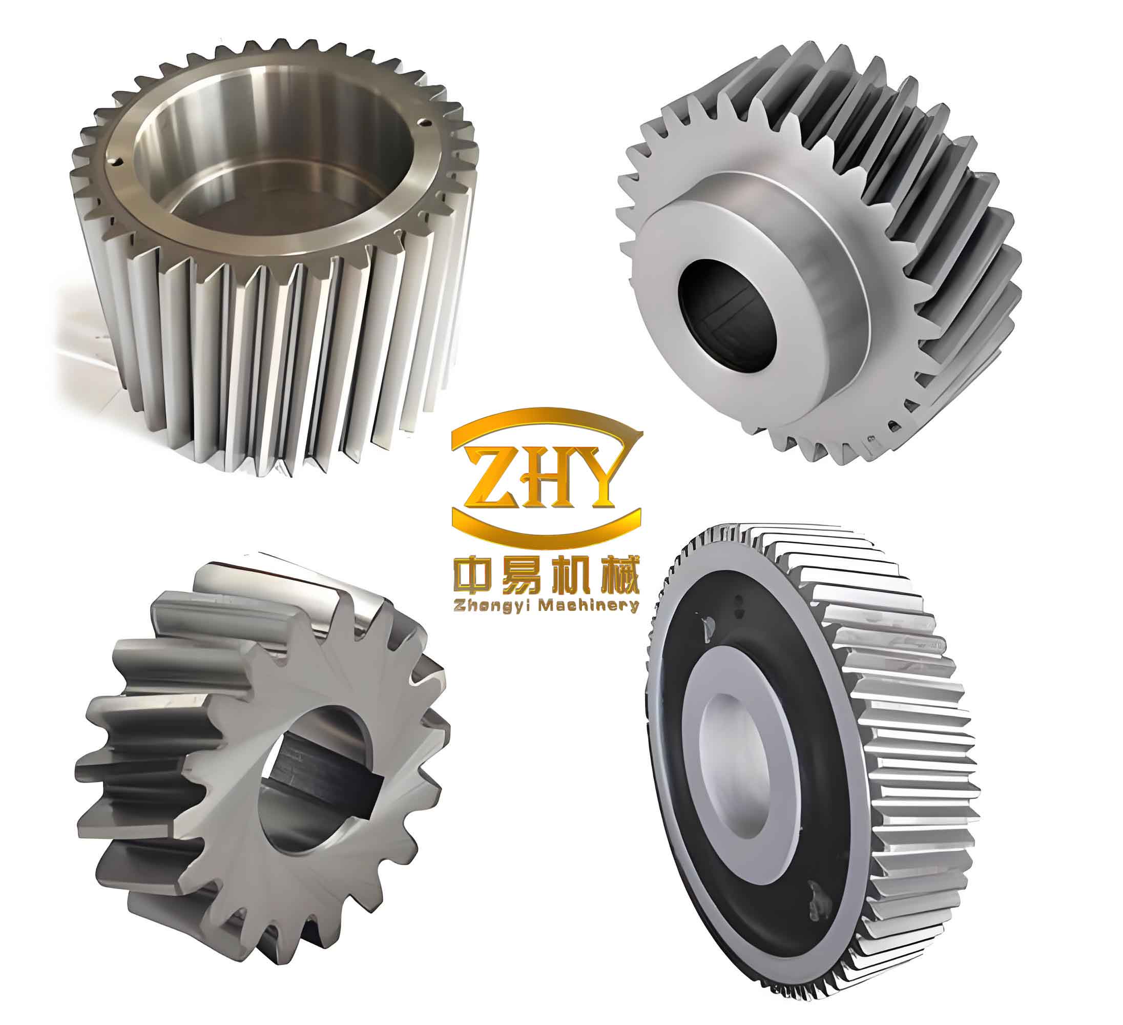
After generating the helical gear teeth, I assembled the driving and driven helical gears and checked for interference. The assembly was clean, so I could use it for finite element analysis. To reduce computation time, I simplified the full helical gear pair to a local tooth model while preserving the meshing region. I imported the simplified geometry into a finite element environment and assigned the material properties. I used 45 steel for both helical gears, with an elastic modulus of \(206\,\mathrm{GPa}\), a density of \(7850\,\mathrm{kg/m^3}\), and a Poisson ratio of 0.3.
I meshed the helical gear pair with tetrahedral elements and refined the contact zone. The mesh contained approximately \(175007\) nodes and \(101994\) elements. I defined the contact between the helical gear teeth as frictional contact with a friction coefficient of 0.05. For the boundary conditions, I fixed the inner surface of the driven helical gear and applied a torque to the driving helical gear. The torque was calculated from the transmitted power and speed:
$$ T = 9.55\times 10^6 \frac{P}{n} $$
With \(P = 14.84\,\mathrm{kW}\) and \(n = 970\,\mathrm{r/min}\), the input torque was:
$$ T = 145908\,\mathrm{N\cdot mm} $$
For contact stress, I used the classical helical gear contact formula:
$$ \sigma_H = Z_H Z_E Z_\epsilon Z_\beta \sqrt{\frac{2KT_1}{b d_1^2}\frac{u+1}{u}} $$
The coefficient values I used in the theoretical calculation are summarized below.
| \(Z_H\) | \(Z_E\) | \(Z_\epsilon\) | \(Z_\beta\) | \(K\) | \(u\) |
|---|---|---|---|---|---|
| 2.43 | 189.8 | 0.784 | 0.983 | 2.15 | 4.8 |
The theoretical contact stress of the helical gear was \(882.2\,\mathrm{MPa}\), while the finite element result was \(802.29\,\mathrm{MPa}\). The two results were close, and both were below the allowable contact stress. I calculated the allowable contact stress from:
$$ [\sigma_H] = \frac{\sigma_{H\lim}}{S_H} Z_N Z_X Z_W Z_{LVR} $$
| \(\sigma_{H\lim}\) (MPa) | \(S_H\) | \(Z_N\) | \(Z_X\) | \(Z_W\) | \(Z_{LVR}\) |
|---|---|---|---|---|---|
| 1150 | 1.0 | 1.0 | 1.0 | 1.0 | 0.92 |
The resulting allowable contact stress was \([\sigma_H] = 1058\,\mathrm{MPa}\). Therefore, the helical gear contact strength was sufficient under the original design.
For root bending stress, I used the classical helical gear bending formula:
$$ \sigma_F = \frac{2KT_1}{b d_1 m_n} Y_{Fa}Y_{Sa}Y_\epsilon Y_\beta $$
| \(K\) | \(Y_{Fa1}\) | \(Y_{Sa1}\) | \(Y_{Fa2}\) | \(Y_{Sa2}\) | \(Y_\epsilon\) | \(Y_\beta\) |
|---|---|---|---|---|---|---|
| 2.15 | 2.77 | 1.57 | 2.18 | 1.79 | 0.68 | 0.82 |
The theoretical bending stress of the driving helical gear was \(255.89\,\mathrm{MPa}\), and that of the driven helical gear was \(229.61\,\mathrm{MPa}\). In the finite element analysis, the maximum root bending stress was \(275.66\,\mathrm{MPa}\) for the driving helical gear and \(215.35\,\mathrm{MPa}\) for the driven helical gear. These values were also below the allowable bending stress. I used:
$$ [\sigma_F] = \frac{\sigma_{F\lim}Y_{ST}}{S_F}Y_N Y_X $$
| \(\sigma_{F\lim}\) (MPa) | \(S_F\) | \(Y_N\) | \(Y_X\) | \(Y_{ST}\) |
|---|---|---|---|---|
| 340 | 1.25 | 1.0 | 0.99 | 2.0 |
The allowable bending stress was \([\sigma_F] = 538.56\,\mathrm{MPa}\). The static analysis therefore confirmed that the initial helical gear design satisfied both contact and bending requirements.
I then moved to dynamic simulation of the helical gear pair. I imported the assembly into a virtual prototyping environment through a Parasolid exchange format. I applied revolute joints between each helical gear and the ground, and I defined solid-to-solid contact between the meshing teeth. The driving helical gear was given a constant angular velocity of \(5820\,\mathrm{deg/s}\), corresponding to \(970\,\mathrm{r/min}\). The driven helical gear received a step torque opposite to its rotation direction. I used the Impact function to compute the contact force:
$$ F_{\mathrm{impact}} = K(q_0-q)^e – C\frac{dq}{dt}\mathrm{STEP}(q,q_0-d,1,q_0,0) $$
The contact stiffness was calculated from Hertz contact theory. For two contacting bodies, I used:
$$ \frac{1}{R} = \frac{1}{R_1}+\frac{1}{R_2} $$
$$ \frac{1}{E} = \frac{1-\mu_1^2}{E_1}+\frac{1-\mu_2^2}{E_2} $$
$$ K = \frac{4}{3}R^{1/2}E $$
For the original helical gear pair, I obtained a contact stiffness of \(K = 698138.27\,\mathrm{N/mm}\). I set the damping coefficient to \(50\,\mathrm{N\cdot s/mm}\), the force exponent to 1.5, the dynamic friction coefficient to 0.05, the static friction coefficient to 0.08, and the penetration depth to \(0.1\,\mathrm{mm}\).
The speed simulation showed that the driving helical gear maintained \(5820\,\mathrm{deg/s}\), while the driven helical gear reached an average of \(1210\,\mathrm{deg/s}\). The theoretical driven speed was \(1212.5\,\mathrm{deg/s}\), so the relative error was only 0.2 percent. The small fluctuation came from the periodic contact and impact behavior of the helical gear teeth.
I also compared the meshing forces with the theoretical helical gear force model:
$$ F_t = \frac{2T_1}{d_1} $$
$$ F_r = \frac{F_t\tan\alpha_n}{\cos\beta} $$
$$ F_a = F_t\tan\beta $$
$$ F_n = \frac{F_t}{\cos\alpha_n\cos\beta} $$
| Force component | Theoretical value (N) | Simulated average (N) | Relative error |
|---|---|---|---|
| Radial force | 2125 | 1964 | 7.5% |
| Tangential force | 5644 | 5836 | 3.3% |
| Axial force | 1495 | 1523 | 1.9% |
| Normal force | 6214 | 6352 | 2.2% |
The simulated forces were close to the theoretical values, which gave me confidence in the helical gear model. To study vibration and noise, I examined the transmission error of the helical gear pair. The transmission error is the difference between the actual and theoretical rotation angles of the driven helical gear:
$$ TE = \theta_{2,\mathrm{actual}} – \theta_{2,\mathrm{theoretical}} $$
For the original helical gear pair, the driving helical gear rotated \(2910\,\mathrm{deg}\), and the driven helical gear rotated \(606.21\,\mathrm{deg}\). The theoretical rotation of the driven helical gear was \(606.25\,\mathrm{deg}\). The relative error was about 0.0066 percent. During stable operation, the transmission error of the original helical gear varied from \(0.0188\,\mathrm{deg}\) to \(0.0437\,\mathrm{deg}\), with a fluctuation amplitude of \(0.0249\,\mathrm{deg}\). This fluctuation is directly related to the vibration and noise of the helical gear pair.
After completing the baseline static and dynamic studies, I built a multi-objective optimization model for the helical gear pair. I chose two objectives: minimizing the mass of the helical gear pair and minimizing its vibration. For the vibration objective, I simplified the helical gear pair to an equivalent mass-spring system along the meshing line. The equivalent mass of the driving and driven helical gears was expressed as:
$$ M_1 = \frac{J_1}{r_{b1}^2},\qquad M_2 = \frac{J_2}{r_{b2}^2} $$
Since the base radius can be written in terms of the normal module, tooth number, helix angle, and transverse pressure angle, the equivalent mass of the helical gear pair became:
$$ M_e = \frac{M_1M_2}{M_1+M_2} = \frac{J_1J_2}{J_1z_2^2+J_2z_1^2}\frac{4\cos^2\beta}{m_n^2\cos^2\alpha_t} $$
The equivalent meshing stiffness of the helical gear pair was:
$$ K_e = \frac{K_1K_2}{K_1+K_2} $$
The natural frequency of the helical gear system was:
$$ f_n = \frac{1}{2\pi}\sqrt{\frac{K_e}{M_e}} $$
The meshing excitation frequency was:
$$ f = \frac{n_1z_1}{60} $$
To reduce vibration, I wanted the natural frequency and the excitation frequency to be as far apart as possible. Therefore, I used the difference between the critical speed and the working speed as the vibration objective:
$$ \min f_1(x) = -(n_{cr}-n_1) $$
For the lightweight objective, I used the volume of the helical gear pair. The volume of a single helical gear was approximated by:
$$ V = \frac{\pi}{4}b\left(d^2-d_p^2\right) $$
Therefore, the volume of the driving and driven helical gears was:
$$ V_1 = \frac{\pi}{4}\left(\frac{m_n^2z_1^2}{\cos^2\beta}-d_{p1}^2\right)b_1 $$
$$ V_2 = \frac{\pi}{4}\left(\frac{m_n^2z_2^2}{\cos^2\beta}-d_{p2}^2\right)b_2 $$
The mass objective was then:
$$ \min f_2(x) = \rho(V_1+V_2) $$
I combined the two objectives using a weighted sum. After normalization, the overall objective function became:
$$ \min f(x) = w_1\frac{f_1(x)}{f_1^*(x)} + w_2\frac{f_2(x)}{f_2^*(x)} $$
$$ w_1+w_2=1 $$
I set \(w_1 = 0.5\) for vibration and \(w_2 = 0.5\) for mass. I selected the normal module \(m_n\), the driving helical gear tooth number \(z_1\), the driven helical gear tooth number \(z_2\), the helix angle \(\beta\), and the face width coefficient \(\phi_d\) as my design variables:
$$ X = \left[m_n,\beta,z_1,z_2,\phi_d\right]^T $$
The geometric constraints I used were:
$$ 2.5 \le m_n \le 6 $$
$$ 8^\circ \le \beta \le 15^\circ $$
$$ 17 \le z_1 \le 24 $$
$$ 90 \le z_2 \le 100 $$
$$ 0.4 \le \phi_d \le 0.9 $$
The performance constraints were based on contact stress and root bending stress:
$$ \sigma_H \le 1058\,\mathrm{MPa} $$
$$ \sigma_{F1} \le 539\,\mathrm{MPa} $$
$$ \sigma_{F2} \le 475\,\mathrm{MPa} $$
I applied a genetic algorithm to solve this multi-objective helical gear optimization problem. I used a population size of 50, a crossover probability of 0.8, a mutation probability of 0.01, and tournament selection. The optimization ran for 102 generations and produced an objective value of about 0.79. After rounding the variables to practical values, the optimized helical gear parameters were:
$$ m_n = 2.5\,\mathrm{mm},\qquad \beta = 12.58^\circ,\qquad z_1 = 21,\qquad z_2 = 91,\qquad \phi_d = 0.55 $$
| Parameter | Before optimization | After optimization |
|---|---|---|
| Normal module \(m_n\) (mm) | 2.5 | 2.5 |
| Driving tooth number \(z_1\) | 20 | 21 |
| Driven tooth number \(z_2\) | 96 | 91 |
| Face width coefficient \(\phi_d\) | 0.87 | 0.55 |
| Helix angle \(\beta\) (deg) | 14.84 | 12.58 |
| Mass of helical gear pair (kg) | 15.68 | 9.47 |
| Vibration objective \(f_1(x)\) | -937.37 | -941.23 |
The mass of the helical gear pair decreased from \(15.68\,\mathrm{kg}\) to \(9.47\,\mathrm{kg}\), a reduction of about 39.6 percent. The vibration objective also improved, indicating a larger separation between the working speed and the critical speed. I then rebuilt the optimized helical gear pair and repeated the static and dynamic simulations to verify the design.
For the optimized helical gear, the finite element contact stress was \(790.56\,\mathrm{MPa}\), which remained below \(1058\,\mathrm{MPa}\). The maximum root bending stress of the driving helical gear was \(212.2\,\mathrm{MPa}\), and that of the driven helical gear was \(169.44\,\mathrm{MPa}\). Both were below the allowable values of \(539\,\mathrm{MPa}\) and \(475\,\mathrm{MPa}\). The optimized helical gear therefore maintained sufficient strength while using less material.
| Result | Before optimization (MPa) | After optimization (MPa) | Relative change |
|---|---|---|---|
| Maximum contact stress | 802.29 | 790.56 | 1.5% |
| Driving root bending stress | 275.66 | 212.2 | 23.0% |
| Driven root bending stress | 215.35 | 169.44 | 21.3% |
For the dynamic verification, I recalculated the helical gear contact stiffness and obtained \(K = 623338.67\,\mathrm{N/mm}\). I also adjusted the driven resistance torque to \(632268\,\mathrm{N\cdot mm}\). The simulation settings were otherwise consistent with the original helical gear analysis. The optimized meshing forces are compared below.
| Force component | Before optimization (N) | After optimization (N) | Relative difference |
|---|---|---|---|
| Radial force | 1964 | 2270 | 15.5% |
| Tangential force | 5836 | 5486 | 5.9% |
| Axial force | 1523 | 1237 | 19.5% |
| Normal force | 6352 | 6068 | 4.5% |
The force distribution changed because the tooth numbers, helix angle, and face width coefficient changed. The normal meshing force decreased, which is favorable for reducing vibration excitation. I also examined the transmission error of the optimized helical gear pair. The driving helical gear rotated \(2910\,\mathrm{deg}\), and the driven helical gear rotated \(671.500\,\mathrm{deg}\). The theoretical driven rotation was \(671.539\,\mathrm{deg}\), giving a very small relative error of about 0.0058 percent.
The optimized helical gear transmission error varied from \(0.0278\,\mathrm{deg}\) to \(0.0499\,\mathrm{deg}\), with a fluctuation amplitude of \(0.0221\,\mathrm{deg}\). In comparison, the original helical gear transmission error fluctuated by \(0.0249\,\mathrm{deg}\). Therefore, the optimized helical gear reduced the transmission error fluctuation by about 11.2 percent. Since a smaller transmission error fluctuation indicates smoother meshing, the optimized helical gear should generate less vibration and noise.
| Item | Before optimization | After optimization | Relative change |
|---|---|---|---|
| Upper transmission error limit (deg) | 0.0437 | 0.0499 | 14.1% |
| Lower transmission error limit (deg) | 0.0188 | 0.0278 | 47.9% |
| Fluctuation amplitude (deg) | 0.0249 | 0.0221 | 11.2% reduction |
My results show that the optimized helical gear pair achieved both goals. The mass of the helical gear pair was reduced by about 39.6 percent, and the transmission error fluctuation was reduced by about 11.2 percent. At the same time, the contact stress and root bending stress remained below the allowable limits. This means that the optimized helical gear can be lighter while still transmitting power safely and with lower vibration and noise.
The static analysis confirmed that the maximum contact stress of the optimized helical gear was \(790.56\,\mathrm{MPa}\), the driving root bending stress was \(212.2\,\mathrm{MPa}\), and the driven root bending stress was \(169.44\,\mathrm{MPa}\). These values provide a reasonable safety margin compared with the allowable contact stress of \(1058\,\mathrm{MPa}\) and the allowable bending stresses of \(539\,\mathrm{MPa}\) and \(475\,\mathrm{MPa}\). The dynamic analysis confirmed that the optimized helical gear had a smaller transmission error fluctuation. Therefore, the genetic algorithm optimization was effective for the lightweight design and vibration reduction of the helical gear pair.
I also observed some limitations in my study. The mass calculation was based on an approximate volume using the pitch diameter, so the real mass of the helical gear may differ slightly from my estimate. The dynamic simulation did not include manufacturing errors or assembly errors, which can affect the actual meshing of a helical gear. In addition, the thermal deformation of the helical gear during operation was not included. These factors should be considered in future work to make the dynamic behavior of the helical gear more realistic. Even with these limitations, my study provides a useful framework for the multi-objective optimization of a helical gear pair. The combination of parametric modeling, finite element analysis, dynamic simulation, and genetic algorithm optimization can help designers obtain a lighter helical gear with lower vibration and noise.
In summary, I designed and evaluated a lightweight helical gear pair with improved vibration performance. I used a parametric involute helical gear model, verified the static contact and bending stresses, simulated the dynamic meshing forces and transmission error, optimized the helical gear parameters with a genetic algorithm, and then rechecked the optimized helical gear. The final helical gear pair had a mass of \(9.47\,\mathrm{kg}\) instead of \(15.68\,\mathrm{kg}\), and its transmission error fluctuation was \(0.0221\,\mathrm{deg}\) instead of \(0.0249\,\mathrm{deg}\). The optimized helical gear therefore achieved the intended lightweight and vibration reduction goals while satisfying strength constraints.