
In the realm of gear manufacturing, gear shaping remains a critical process for producing external gears, multi-stage gears, and internal gears. The advancement in gear shaping cutter technology has garnered significant interest from tool manufacturers, driven by the need for high precision and efficiency. Modern gear shaping machines and cutters can achieve cutting speeds and efficiencies that were once unimaginable. However, in many contexts, the design of gear shaping cutters still relies heavily on manual methods, and the manufacturing process often involves trial-and-error adjustments, leading to unnecessary waste. Therefore, developing a practical computer-aided design (CAD) system for gear shaping cutters, tailored to existing machining conditions, is an urgent and essential task. This article explores a programmatic design approach for involute helical gear shaping cutters, focusing on the complexities of spatial meshing in gear shaping operations.
The cutting process for helical gears using a gear shaping cutter involves spatial meshing, which complicates calculations due to the three-dimensional nature of the engagement. The gear shaping cutter and workpiece interact like a pair of meshing gears, rotating while cutting. Thus, the cutter’s tooth profile resembles that of a gear, with features such as the pitch circle, base circle, and a defined pressure angle. However, the cutter incorporates cutting angles, including rake and relief angles, to facilitate material removal. These angles influence the tooth shape across different sections of the cutter, making it essentially a variable-profile gear. To ensure that the tooth profile remains unaffected after regrinding, the gear shaping cutter is designed as a continuous variable-profile gear, where the tip diameter and tooth thickness vary across sections perpendicular to the cutter axis, resulting in a continuous change in the modification coefficient. This variation generates relief angles on both the tip and flank of the cutter. The section nearest the front face has a larger modification coefficient, while the section near the rear face has a smaller one, with an intermediate section—called the original section—having a modification coefficient of zero. This design principle underpins the effectiveness of gear shaping in producing accurate helical gears.
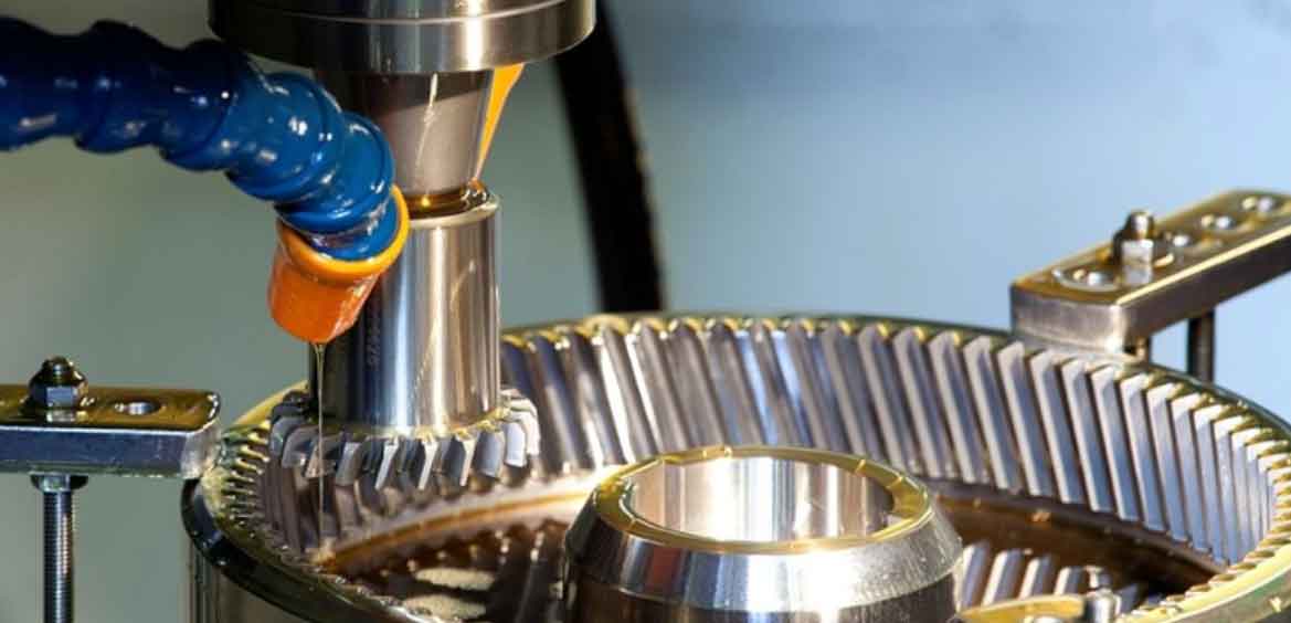
The selection and limitations of the modification coefficient for a gear shaping cutter are crucial, as the cutter behaves like a variable-profile gear. The modification must be constrained at the tooth root, tip, and transition curves to avoid issues such as tooth weakening or interference. When designing a gear shaping cutter, choosing an appropriate modification coefficient is a primary task. A new cutter should ideally use a large modification coefficient \( x_0 \) for several reasons: it increases the number of possible regrinds, extending the cutter’s lifespan; and it enhances the flank rake angle at the tip, improving the surface quality of the machined gear. However, increasing \( x_0 \) is limited by factors such as tooth tip thinning, which reduces durability, and the risk of transition curve interference in the machined gear. Thus, the maximum modification coefficient \( (x_0)_{\text{max}} \) should be selected under these constraints. Conversely, when the cutter is worn to its strength limit, the minimum modification coefficient \( (x_0)_{\text{min}} \) must be checked to prevent issues like undercutting or topping in the workpiece. These considerations ensure that the gear shaping process yields合格的 gears, and they form the basis for the CAD system’s validation steps.
To address these complexities, a computer-aided design methodology for helical gear shaping cutters has been developed. This approach involves a systematic program that automates parameter calculations and validations. The design process begins with inputting initial parameters, some of which are based on empirical values derived from extensive experimental data to ensure reliability. After computation, the program performs successive checks against constraints such as tooth strength, interference, and cutting limits. If conditions are met, it proceeds; otherwise, parameters are adjusted iteratively until all criteria are satisfied. The flowchart below summarizes this process, highlighting the iterative nature of gear shaping cutter design.
The core of the CAD system is implemented using programming languages like Visual C++, which facilitates precise calculations and integration with CAD software. For instance, key calculations involve determining the cutter’s pressure angle, curvature radii, and diameters across different sections. Consider the following formulas used in the program:
- Pressure angle for worn cutter: $$ \alpha_{foj} = \alpha_{fn} + 1 \times \frac{\pi}{180} $$ where \( \alpha_{fn} \) is the nominal pressure angle, and \( \alpha_{foj} \) represents the pressure angle of the worn cutter in radians.
- Minimum curvature radius for worn cutter: $$ \rho_{\text{min}j} = \frac{(d_b + d_{bo}) \tan(\alpha_{foj})}{2} – \rho_{\text{max}} $$ Here, \( d_b \) is the base diameter of the gear, \( d_{bo} \) is the base diameter of the cutter, and \( \rho_{\text{max}} \) is the maximum curvature radius of the gear. If \( \rho_{\text{min}j} \leq 0 \), topping occurs, indicating failure.
- Maximum curvature radius for worn cutter: $$ \rho_{\text{max}j} = \rho_{\text{min}j} + l_n $$ where \( l_n \) is the length of the involute profile.
- Effective tip diameter for worn cutter: $$ d_{eojp} = \sqrt{d_{bo}^2 + 4 \rho_{\text{max}j}^2} $$
- Tip diameter for worn cutter: $$ d_{eoj} = \frac{d_b + d_{bo}}{\cos(\alpha_{foj})} – (d_e – 2h) $$ with \( d_e \) as the gear tip diameter and \( h \) as the addendum.
- Radial overrun for worn cutter: $$ d_{atj} = \frac{d_{eoj} – d_{eojp}}{2} $$ If \( d_{atj} \leq 0 \), transition curve interference happens, necessitating redesign.
These equations are embedded in the CAD program to automate checks, ensuring that the gear shaping cutter design avoids common pitfalls. The program’s interface allows users to input parameters and view results, such as those for protuberances and tip relief, as shown in runtime displays. This integration streamlines the gear shaping cutter design process, reducing manual effort and errors.
To further elucidate the design parameters and constraints, the following tables summarize key aspects of helical gear shaping cutter design. These tables aid in visualizing the relationships between variables and their limits, which are critical for successful gear shaping operations.
| Parameter | Symbol | Description | Typical Range |
|---|---|---|---|
| Modification Coefficient | \( x_0 \) | Determines tooth profile variation across sections | -0.5 to 2.0 |
| Pressure Angle | \( \alpha \) | Angle defining tooth flank inclination | 20° to 25° |
| Helix Angle | \( \beta \) | Angle of gear teeth relative to axis | 10° to 45° |
| Number of Cutter Teeth | \( z_0 \) | Affects cutter size and meshing conditions | 10 to 100 |
| Rake Angle | \( \gamma \) | Front clearance angle for cutting | 5° to 10° |
| Relief Angle | \( \alpha_r \) | Back clearance angle for durability | 3° to 6° |
| Constraint Type | Condition | Mathematical Expression | Impact on Design |
|---|---|---|---|
| Tooth Tip Thinning | Tip width must exceed minimum for strength | \( s_a \geq s_{\text{min}} \) | Limits \( x_0 \) increase |
| Transition Curve Interference | Cutter tip must clear gear root | \( \rho_{\text{min}j} > 0 \) | Prevents undercutting |
| Topping | Gear tip must not interfere with cutter root | \( d_{atj} > 0 \) | Ensures proper meshing |
| Strength Limit | Stress at tooth root must be below allowable | \( \sigma \leq \sigma_{\text{allow}} \) | Determines \( (x_0)_{\text{min}} \) |
The CAD system’s program flow involves multiple validation steps to ensure that the gear shaping cutter meets all operational requirements. For example, after computing the worn cutter’s parameters, the program checks for topping and interference using conditional statements. If issues are detected, it prompts redesign, thereby automating the iterative refinement inherent in gear shaping cutter design. This automation is pivotal for reducing design time and improving accuracy, as manual calculations for helical gear shaping are prone to errors due to the spatial meshing complexities.
In practice, the design software generates detailed drawings for the gear shaping cutter, which can be used for in-house manufacturing or outsourcing. The integration with CAD environments like AutoCAD allows for parametric drawing creation, where design parameters are automatically populated into tables on the drawing sheet. This seamless workflow enhances efficiency, as designers can quickly produce cutter specifications tailored to specific gear shaping applications. The software’s ability to handle complex calculations, such as those for protuberances and tip relief, further underscores its utility in modern gear shaping cutter design.
The benefits of this computer-aided design approach are manifold. By automating the design process, it shortens the product development cycle by over 80%, leading to significant economic gains. Moreover, the precision afforded by the CAD system reduces material waste and improves the quality of machined gears, making gear shaping more sustainable and cost-effective. The software has been refined through theoretical research and practical application, earning praise from designers and machinists alike for its reliability and ease of use in gear shaping tasks.
Looking ahead, the future of gear shaping cutter design lies in further integration with manufacturing systems. Expanding the CAD software to encompass a holistic “design, manufacturing, and machining” system could revolutionize gear production. Such an integrated system would enable real-time adjustments based on machining feedback, optimizing cutter performance for specific gear shaping operations. Additionally, advancements in materials science and cutting technologies could be incorporated into the design algorithms, allowing for cutters tailored to high-speed or hard-material gear shaping. The ongoing evolution of gear shaping techniques promises to enhance productivity and precision in gear manufacturing worldwide.
In conclusion, the computer-aided design of helical gear shaping cutters addresses the intricate challenges posed by spatial meshing in gear shaping. Through programmatic methods that incorporate rigorous calculations and validations, designers can efficiently produce cutters that meet stringent performance criteria. The use of tables and formulas, as demonstrated, facilitates a clear understanding of parameter interactions and constraints. As technology progresses, the integration of CAD with broader manufacturing systems will further elevate the efficacy of gear shaping, solidifying its role as a cornerstone of gear production. This research underscores the importance of innovation in gear shaping cutter design, paving the way for more advanced and efficient gear shaping solutions in the industry.