
Because the processing technology and cutting tools of the modified gear are not different from those of the standard gear, in order to meet and adapt to the actual needs of production, the modified gear not only has the characteristics of wide application and accurate transmission of the standard gear, but also plays an irreplaceable role of the standard gear under many special environmental conditions. By considering the change of installation center distance, the simulation test of modified gear is realized by using hobbing model simulation method.
The method of machining gears in this way is called the modified gear correction method. The gears processed by this method are called modified gears. The distance XM that the rack tool is close to or away from is called radial displacement, which is called displacement for short. Where, M is the modulus and X is the radial displacement coefficient, which is referred to as the displacement coefficient for short. The profile shape of modified gear is related to the number of teeth, modulus, modification coefficient and pressure angle.
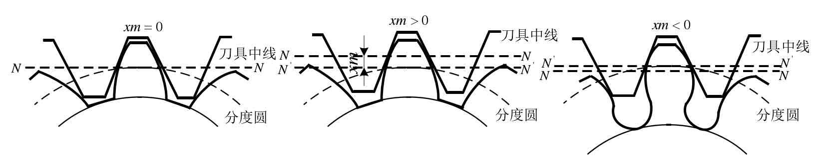
As shown in the figure, there are three situations for the center line NN of the rack tool relative to the indexing circle of the processed gear: when NN is tangent to the indexing circle of the processed gear, the processed gear is called the standard gear; When NN is far away from the rotation center of the processed gear, X is positive, which is called positive displacement gear; When NN is close to the rotation center of the processed gear, X is a negative value, which is called negative displacement gear.
The minimum number of teeth without undercutting of standard gear is:
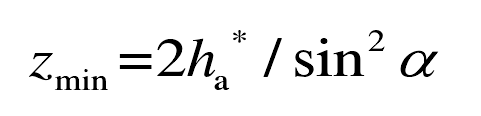
For the simulation test of modified gear, according to the basic calculation parameters of hob and gear tooth surface in table 3-1, take the tooth crest height coefficient h * a = 1 and the pressure angle α= 27.5 °, Zmin = 10.
Minimum displacement coefficient to avoid undercutting: when machining gear with rack cutter, in order to avoid undercutting, the displacement XM is required:
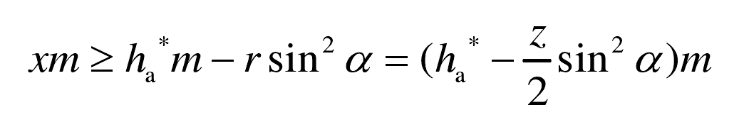
Where:
M — module of gear (mm);
Z — number of teeth of gear;
R – radius of indexing circle of gear (mm)
Combined with the formula, the minimum displacement coefficient to avoid undercutting of the processed gear is:
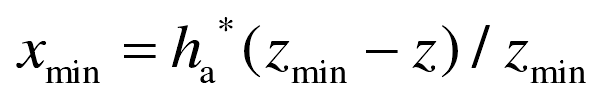
Take the number of processed teeth z = 28 and modulus M = 3mm to obtain the minimum displacement coefficient xmin = -1.8, and the displacement meets XM ≥ – 5.4mm.
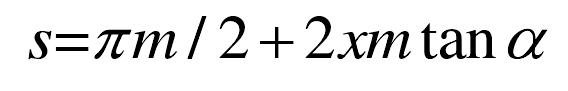
Tooth thickness s of positive displacement gear:
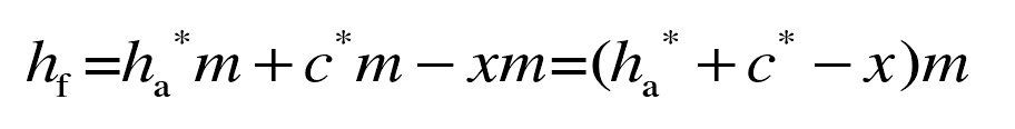
The tooth root height of the positive displacement gear is XM lower than that of the standard gear, that is:
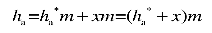
The addendum height of the positive displacement gear is XM higher than that of the standard gear, that is:
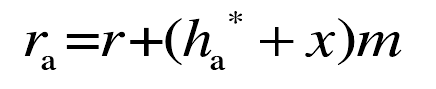
Radius of addendum circle of positive displacement gear RA:
Compared with the standard gear, the module, number of teeth and pressure angle of the modified gear do not change. The tooth thickness, tooth top height and tooth top circle of positive displacement gear become larger, and the tooth root height becomes smaller. The negative modification gear is opposite to the positive modification gear.