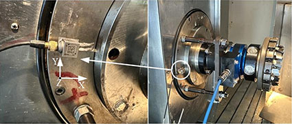
The main spindle system characteristics of bevel gear milling machine are matched with process parameters to improve milling efficiency and enhance tooth surface machining quality. Based on the basic principles of machine tool dynamics analysis, a finite element dynamic model of the milling machine spindle system is established using the finite element method. Based on this, numerical methods are used to complete the response analysis of the machine tool under different machining parameters. The correctness of the constructed numerical model and the effectiveness of the selected process parameter combination are verified through finite element simulation and experimental verification. Firstly, based on the finite element dynamics theory and Timoshenko beam theory, a dynamic model of the milling machine spindle system is established. By solving the motion differential equation, the natural frequency of the spindle system is obtained Rate and vibration mode; On this basis, the dynamic response of bevel gears in various directions is calculated using the mode superposition method and numerical integration method, including harmonic response analysis and transient response analysis. At the same time, this article also used finite element software to simulate and calculate the response under the same conditions as the numerical model, in order to verify the accuracy of the numerical model and lay the foundation for future research on process parameter matching using numerical models. Due to the fact that cutting force is the main source of excitation force in the gear milling process, gear this article derives three directions of cutting force components for gear milling based on oblique cutting theory, establishes a theoretical cutting force model, and analyzes the influence of different process parameters on the amplitude of cutting force on this basis. The bevel gear was then used to calculate the cutting force under different process parameter combinations using finite element cutting simulation software AdvantEdge FEM. By inputting the results of the theoretical cutting force model into the finite element numerical model for analysis, a set of process parameters that match well with the dynamic characteristics of the spindle system were obtained for the bevel gear. Finally, this article conducted processing experiments under this set of process parameters to verify the matching effect with the dynamic characteristics of the spindle system.
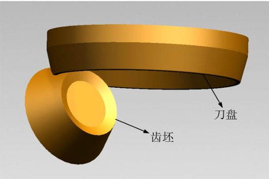
Various sources of excitation are analyzed during the milling and cutting process, and cutting force is the main source of excitation in this process. On this basis, based on the theory of oblique cutting and the relative position relationship between the cutter head and the gear blank during gear milling, the calculation formula for cutting forces in various directions when machining small wheels using the expansion method was derived, and a theoretical cutting force model was established. Based on this model, the cutting force amplitude under different process parameters was calculated, laying the foundation for process parameter optimization. At the same time, finite element cutting simulation software AdvantEdge FEM was used to calculate the cutting forces in different directions at different speeds and feed rates, and the corresponding frequency components were analyzed to study the influence of different process parameters on cutting forces and cutting force frequencies. The spindle system of a gear milling machine includes components such as shafts, gear bearings, and milling cutters, and its dynamic characteristics have a direct impact on milling efficiency and tooth surface quality. The structural diagram of the spindle system of a certain gear milling machine under study consists of components such as the spindle, front bearing, lubricating oil circuit, cooling groove, rear bearing, and electric spindle housing. The structures that have a significant impact on the dynamic characteristics of the spindle system include the spindle, bearings, and cutterhead.
The spindle system of the gear milling machine, as the core component of the machine tool, is responsible for rotating the cutting tools during the machining process
The key task is to transmit cutting force and achieve high-precision positioning. These sudden and periodic loads may cause problems such as vibration, resonance, deformation, etc., which in turn affect machining accuracy, gear tooth surface quality, and tool life. In order to ensure the optimal machining performance of the machine tool, it is not only necessary to pay attention to its static stiffness and steady-state dynamic characteristics, but also to conduct in-depth research on the transient impact loads that the spindle system is subjected to in actual operation. Transient dynamics analysis considers the non steady and sudden external loads that the spindle system is subjected to in a short period of time, which may originate from factors such as sudden impacts during cutting, dynamic loads during tool workpiece interaction, machining parameters,gear feed and retract of machined parts, and changes in part shape and thickness during machining. These complex and ever-changing dynamic environments place higher demands on the performance and stability of the spindle system. By delving into the transient response of the spindle system, we can understand the dynamic behavior of the spindle system under actual operating conditions,gear identify potential vibration problems, and then select appropriate process parameters or develop targeted optimization plans.


