
For a pair of bevel gears, to maintain pure rolling contact means that there is no relative sliding motion between their tooth surfaces at the contact point, that is:
According to the meshing principle of bevel gear, for bevel gear, the relative sliding speed is 0 only when the indirect contact of tooth surface is located on the pitch line, that is, the equation can be established. At the same time, this means that the moving track of the contact point in the bevel gear dynamic coordinate system is located on the respective pitch cones of the two wheels. According to the previous chapter, Γ 1 and Γ 2 is the contact trace of two tooth surfaces respectively. Therefore, to design continuous pure rolling contact bevel gear, based on the spatial conjugate curve method, it means Γ 1 and Γ 2 needs to be on the pitch cone.
Mathematically, the cone equation can be expressed as:
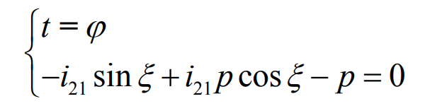
Here, P = tan( δ),δ Represents the cone angle and π / 2 > δ > 0
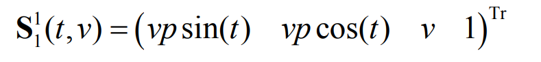
By the formula, Γ 1 can be expressed as:

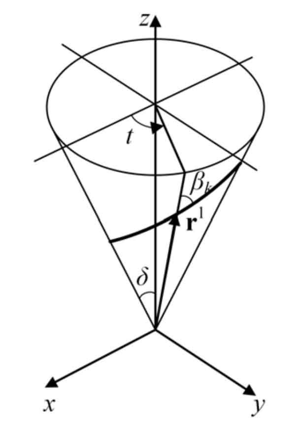
here, Γ 1 can be any conical curve, and T represents the conical angle parameter, as shown in the figure.
Obviously, when the formula is satisfied, the meshing equation is arbitrary Γ Any normal vector of 1 holds.
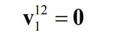
According to the formula, under the coordinate system S1, the relative speed is:
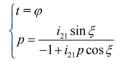
By substituting the formula into the equation, the first condition that continuous pure rolling bevel gear must meet can be obtained:
The formula can also be written in another form:
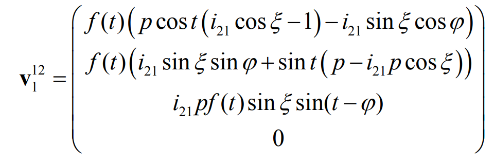
Finally, from the formula, we can get Γ Conjugate curve of 1 Γ 2:
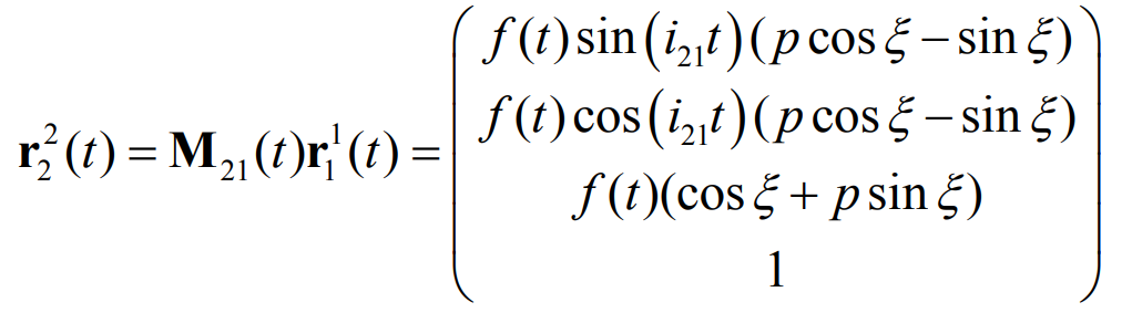
As can be seen from the formula, Γ 1 and Γ 2 has similar expression. In fact, in the formula, if i21t is regarded as t, f (T) (COS) ξ+ psin ξ) As f (T), (PCOS) ξ- sin ξ)/ (cos ξ+ psin ξ) As P, the formula has the same expression. So, Γ 1 and Γ 2 is the same type of conical curve.