

After obtaining the cutting adjustment parameters and cutter head parameters of the large and small gears of spiral bevel gear, the theoretical tooth surface point coordinates of the large and small gears can be solved by using the spiral bevel gear meshing theory, which can be imported into the three-dimensional modeling software. After reconstructing the tooth surface, the three-dimensional solid model of spiral bevel gear can be created, as shown in Figure 1. The geometric model is imported into the finite element preprocessing software HyperMesh to divide the finite element mesh. Firstly, it is divided into multiple single tooth models, and two-dimensional quadrilateral meshes are divided on the end face and each side of the tooth, as shown in Figure 2. Then, the end mesh is scanned along the side mesh to obtain the hexahedral mesh, as shown in Figure 3.
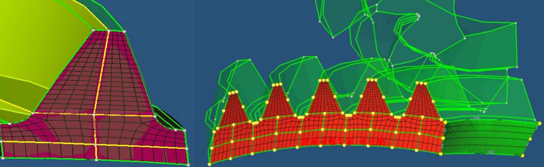
Considering that the tooth surface distortion of spiral bevel gear is large and the distortion is prominent when meshing, the linear reduced integral element (c3d8r) with less influence on the analysis accuracy is selected. In order to analyze the calculation results of a complete meshing cycle in the case of multi tooth meshing, and make the calculation amount not too large, the five tooth finite element model is used to calculate, and the number of grids in the direction of tooth length and tooth height is 100×20.

In order to facilitate the processing of later calculation results, contact pairs are established respectively according to the order and corresponding relationship of the tooth surface of the driving and driven gears entering meshing. In the calculation, other degrees of freedom except the rotation of the axis of the driving and driven wheels are constrained. And set the following analysis steps:
Step 1, eliminate the gap during the initial meshing of the driving and driven gears, apply a small rotation angle along the rotation direction of the driven wheel, restrict all degrees of freedom of the driving wheel, establish a stable contact relationship between the contact tooth surface, and improve the success rate of convergence of the initial iterative calculation;
Step 2, cancel the micro rotation angle applied by the driven wheel around its rotation direction;
Step 3, release the axial constraint of the driving wheel, apply the rotation angle to the driving wheel when calculating the meshing stiffness of spiral bevel gear, apply the speed to the driving wheel when calculating the meshing impact, and apply the reverse torque to the driven wheel.
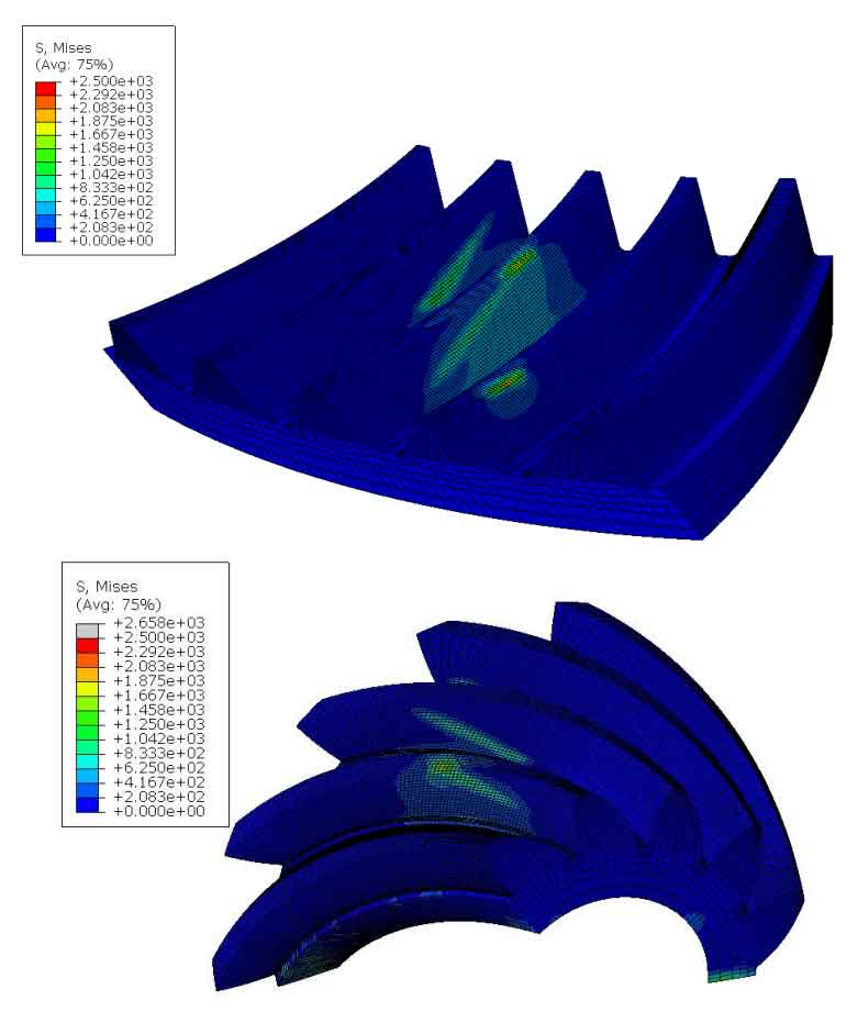
Submit the cloud diagram of the stress of the large and small wheels at each meshing moment of the spiral bevel gear, as shown in Figure 4. An obvious instantaneous contact ellipse can be observed on the tooth surface, and three teeth participate in meshing at each instant, which verifies the correctness of the finite element contact model.