1. Tooth contact analysis of helical gear pairs
During the meshing process of the driving and driven gears, the two tooth surfaces are in continuous tangent contact. In the fixed coordinate system Sf, the two meshing tooth surfaces have a common contact point, and there must be a common position vector and a common normal vector on the contact point, which satisfies:

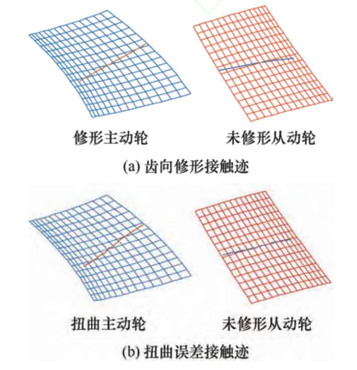
Determine the position vector and normal vector of the contact point through the TCA program, and calculate the position of the contact point on the tooth surface. Figure 1a shows the contact trace of the standard tooth profile modified helical gear, and Figure 1b shows the contact trace of the helical gear with distortion error. Due to the presence of distortion, the contact trace on the tooth surface is uneven.
The ideal helical gear transmission is conjugate, that is, when the driving wheel rotates at a certain angle, the driven wheel also rotates at the corresponding angle. However, due to manufacturing errors and deformation during torque transmission, helical gears cannot achieve uniform angle transmission. Therefore, the transmission error is defined as the deviation of the large wheel from its ideal position when the small wheel rotates at an angle, expressed as:

In the formula, z1 and z2 are the number of teeth of the driving and driven wheels; φ 1 φ 2 is the actual turning angle; φ 1 (0) and φ 2 (0) is the initial turning angle.
The modified tooth surface is a point contact at any meshing moment. Due to the elastic deformation of the tooth surface, the contact area is elliptical, and the center of the ellipse is the instantaneous contact point. The size and direction of the major axis of the contact ellipse are determined by the main curvature and direction of the contact surface, as well as the elastic coefficient of the contact surface, with a constant of 0.006 35. The calculation method for the main direction and main curvature of the contact points on the tooth profile modification gear and helical gear in point contact staggered shaft helical gear transmission is as follows, where i is 1 or 2, representing the driving wheel or driven wheel.
The principal curvature of the meshing point satisfies the following equation:
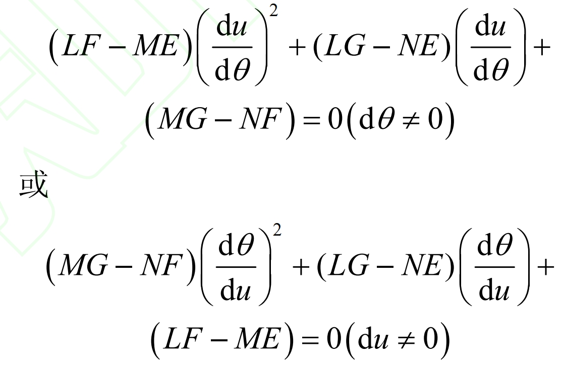
In the formula, E, F, G and L, M, E are the first and second basic quantities of the tooth profile surfaces of modified helical gears and standard helical gears, respectively.
According to the formula, du/d can be calculated θ Or d θ/ Therefore, the principal curvature and principal direction of the meshing point can be obtained as follows:
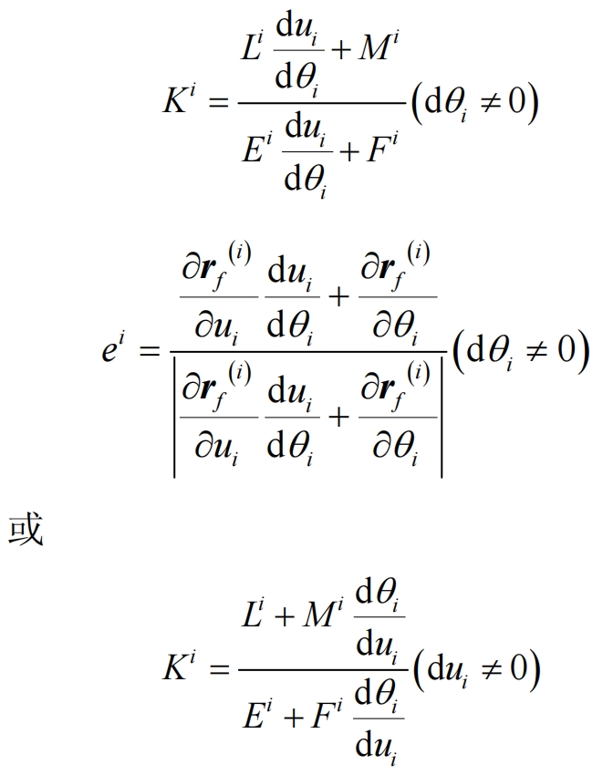
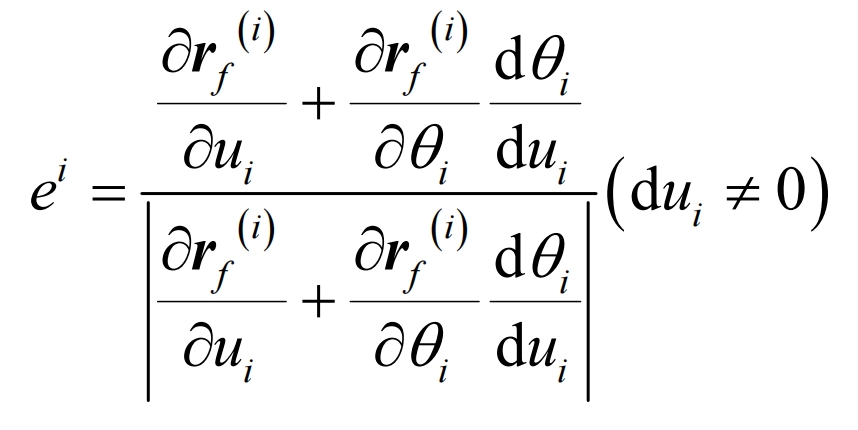
By solving the principal curvature and principal direction of the meshing point using the above formula, the long and short axis radii of the contact ellipse can be obtained.
2. The impact of main design parameters on distortion
| Parameters | Modified driving wheel | Driven wheel |
| Module mn/mm | 5 | 5 |
| Normal pressure angle α N/(°) | 20 | 20 |
| Spiral angle β/ (°) | 20 | 10 |
| Number of teeth z | 31 | 43 |
| Tooth width b/mm | 55 | 60 |
Taking the modification driving wheel in Table 1 and the worm grinding wheel tool in Table 2 as examples, a tooth surface model was established in Matlab. For ease of observation, a drum shape modification amount of 2 mm was given, and the tooth direction modification tooth surface and twisted tooth surface are shown in Figure 2.
| Parameters | Numerical value |
| Pitch diameter mm | 260 |
| Head count | 1 |
| Width mm | 180 |
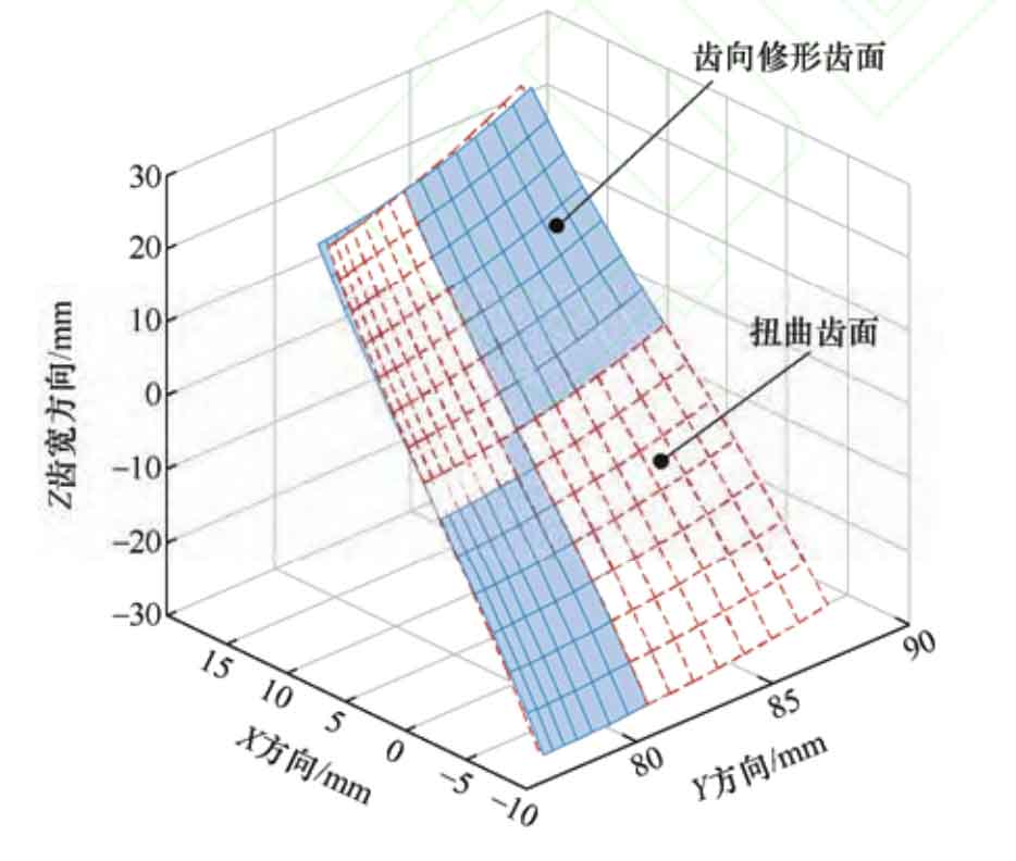
From Figure 2, it can be seen that the slope deviation of the upper and lower tooth surfaces of the helical gear is the largest, and the slope deviation of the middle end face is the smallest. Therefore, the distortion phenomenon near the upper and lower end faces of helical gears is more severe. The calculation formula for tooth surface distortion can be expressed as:

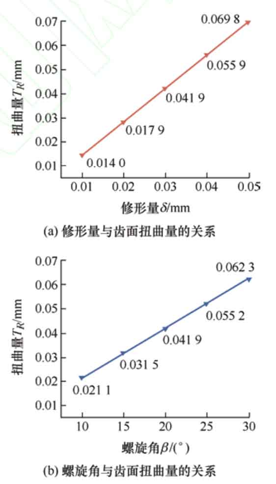
In the formula, the distortion of the modified tooth surface is related to the length of the grinding meshing line B1B2, and the helix angle of the helical gear base circle β b. Tooth profile correction amount δ It is positively correlated and negatively correlated with tooth width b. Therefore, when designing tooth profile modification helical gears, the influence of the four factors in the equation can be fully considered to effectively reduce the distortion phenomenon of the modified helical gears. Due to B1B2 containing β The function of, β B contains helix angle β The function of, and the amount of shape modification δ And helix angle β It is an important parameter for tooth profile modification, so the modification amount is selected δ And helix angle β As the main design parameter. Taking the modification driving wheel in Table 1 and the worm grinding wheel tool in Table 2 as examples, when the helix angle is 20 º, the modification amount is changed in order of 10 μ m. 20 μ m. 30 μ m. 40 μ m. 50 μ m. The relationship between the calculated modification amount and the tooth surface distortion amount is shown in Figure 3a. As the modification amount increases, the tooth surface distortion amount also increases. Under the same helical gear parameters, select a modification amount of 30 μ m. Change the helix angle to 10 º, 15 º, 20 º, 25 º, and 30 º in sequence. Calculate the relationship between helix angle and tooth surface distortion as shown in Figure 3b. As the helix angle increases, the tooth surface distortion increases.
3. Analysis of the Impact of Main Design Parameters on Transmission Errors
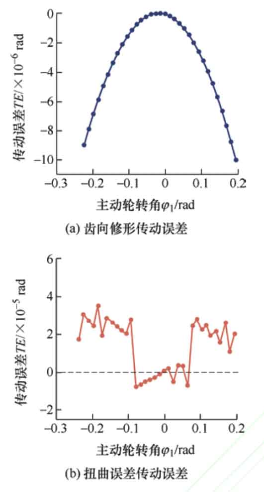
Choose a helix angle of 20 º and a shaping amount of 30 μ Draw the transmission error curve, as shown in Figure 4. Figure 4a shows the transmission error curve of the tooth profile modification drum shaped teeth, which is manifested as a symmetrical parabola, and the acceleration magnitude of meshing in and out is basically the same. The meshing process of the driven wheel is stable. The points on the transmission error curve are all in the horizontal axis, and the transmission error is less than 0, indicating that the driven wheel is in an ideal motion state throughout the entire meshing process. Figure 4b shows the error curve of drum tooth transmission with distortion error. When meshing in and out, due to the presence of distortion, the curve appears serrated and does not transition smoothly. However, the distortion phenomenon is reduced near the middle of the tooth surface, making it smoother. At the moment of meshing in and out, the transmission error is greater than 0, that is, the driven wheel rotates ahead of the theoretical value, and interference occurs during the meshing of the helical gear, causing vibration and noise during the transmission process. Transmission error is the excitation source of vibration and noise in helical gear systems, therefore, distortion error leads to unstable and noisy tooth profile modification helical gear transmission.
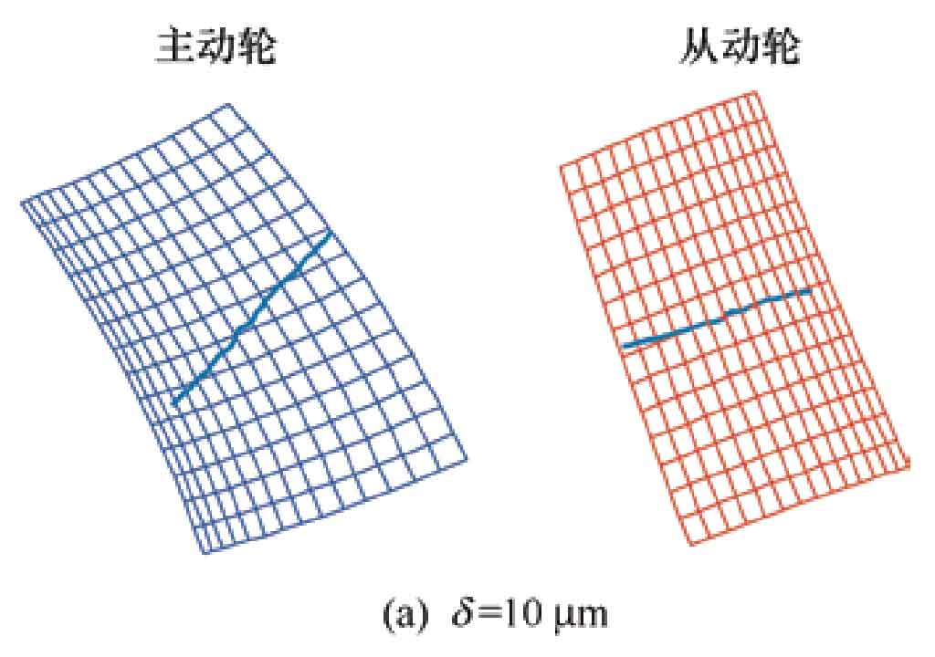
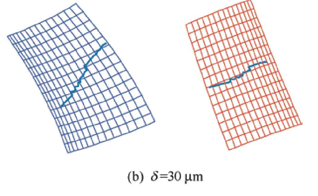
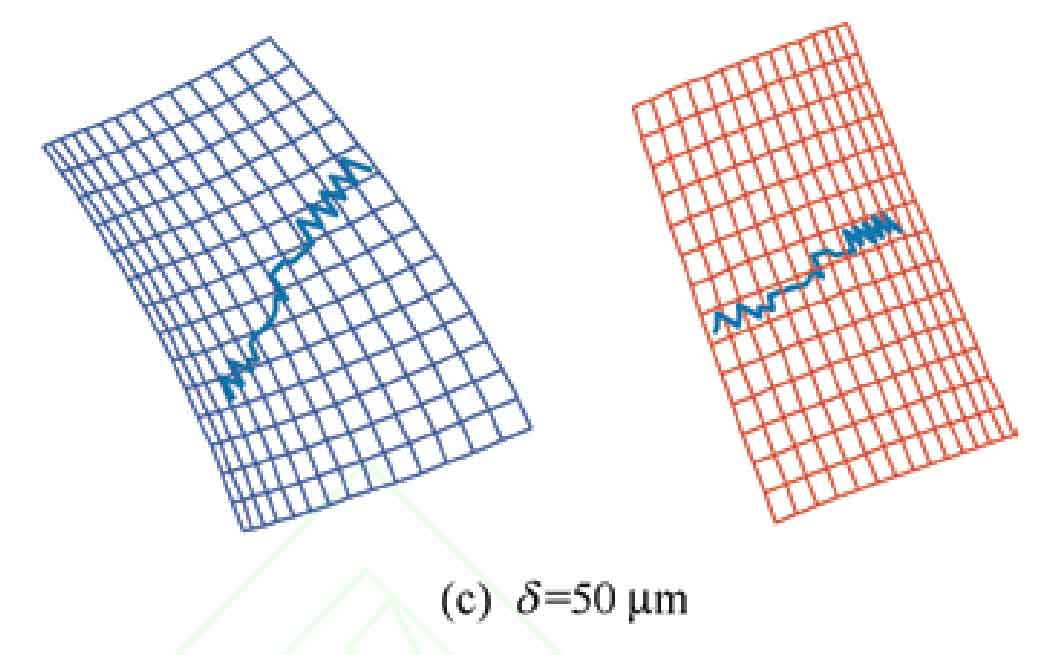
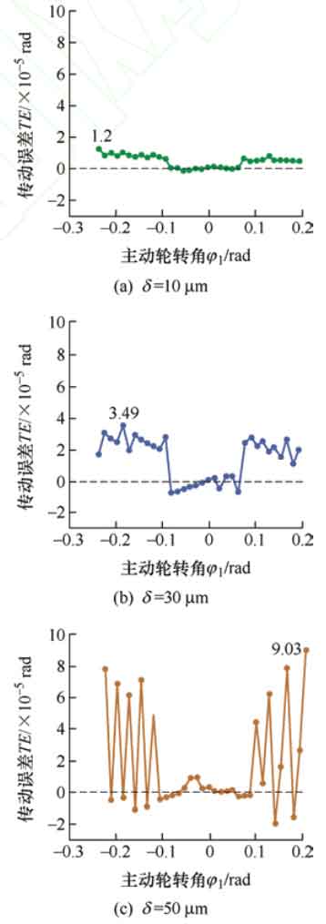
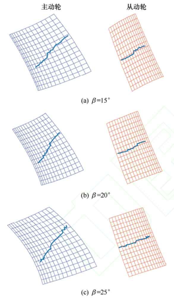
When the helix angle is 20 º, the shaping amount is 10 respectively μ m. 30 μ m. 50 μ The contact trace at time m is shown in Figure 5, and it can be seen that as the amount of modification increases, the serrated process of the contact trace from meshing in to meshing out becomes more pronounced μ The contact trace at m is the smoothest. The transmission error curve is shown in Figure 6, with a modification amount of 10 μ At m, the distortion phenomenon is not obvious, so the transmission error curve changes relatively smoothly. But as the amount of modification increases, the degree of distortion intensifies, and the amplitude of transmission error significantly increases, and the change in amplitude becomes more and more obvious at the moment of meshing in and out, at a modification amount of 50 μ At m, the curve exhibits the most severe sawtooth shape, and the amplitude of transmission error changes dramatically. In the middle stage of meshing, the amplitude of transmission error does not change significantly and is close to 0. Therefore, an increase in the amount of modification will lead to more pronounced noise and vibration phenomena during meshing of helical gears.
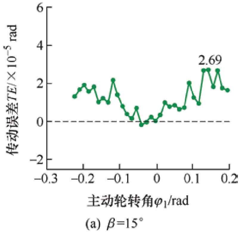
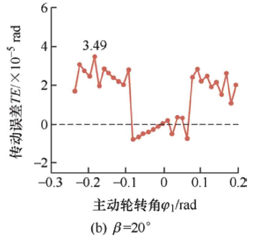
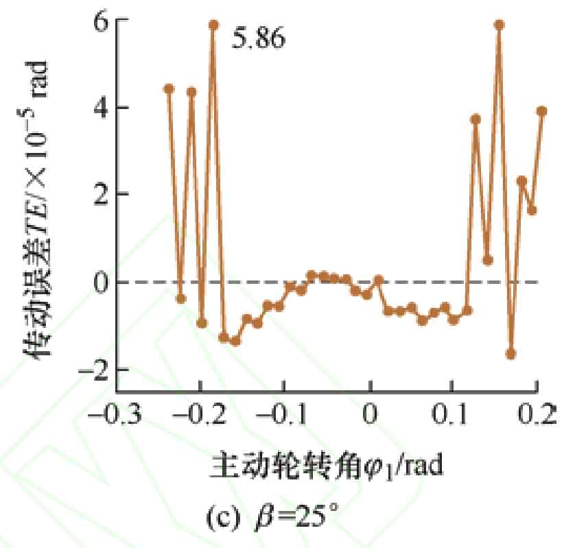
When the shaping amount is 30 μ m. The contact traces at helix angles of 15 º, 20 º, and 25 º are shown in Figure 7. Due to the smaller range of helix angle values compared to the range of shape correction, the changes in contact traces and transmission error amplitudes under the three helix angles are not significant. But it can also be seen that the degree of change in the contact trace is different, and as the helix angle increases, the contact trace of the modified active gear tooth surface containing distortion error changes more significantly. The transmission error curve is shown in Figure 8. As the helix angle increases, the angle between the contact trace and the end section increases, leading to an increase in the length of the contact trace and a faster entry into smooth meshing. The part of the transmission error less than 0 within one cycle also increases. But during the meshing in and out stage, as the helix angle increases, the amplitude of transmission error also increases, leading to an increase in vibration and noise. Corresponding to the transmission error curve, β At 15 º, there is fluctuation in the contact trace throughout the entire meshing process, but it is not significant; β At 25 º, the change in meshing position is more pronounced than in the middle of meshing.
4. Analysis of the influence of main design parameters on contact ellipses
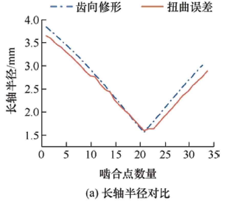
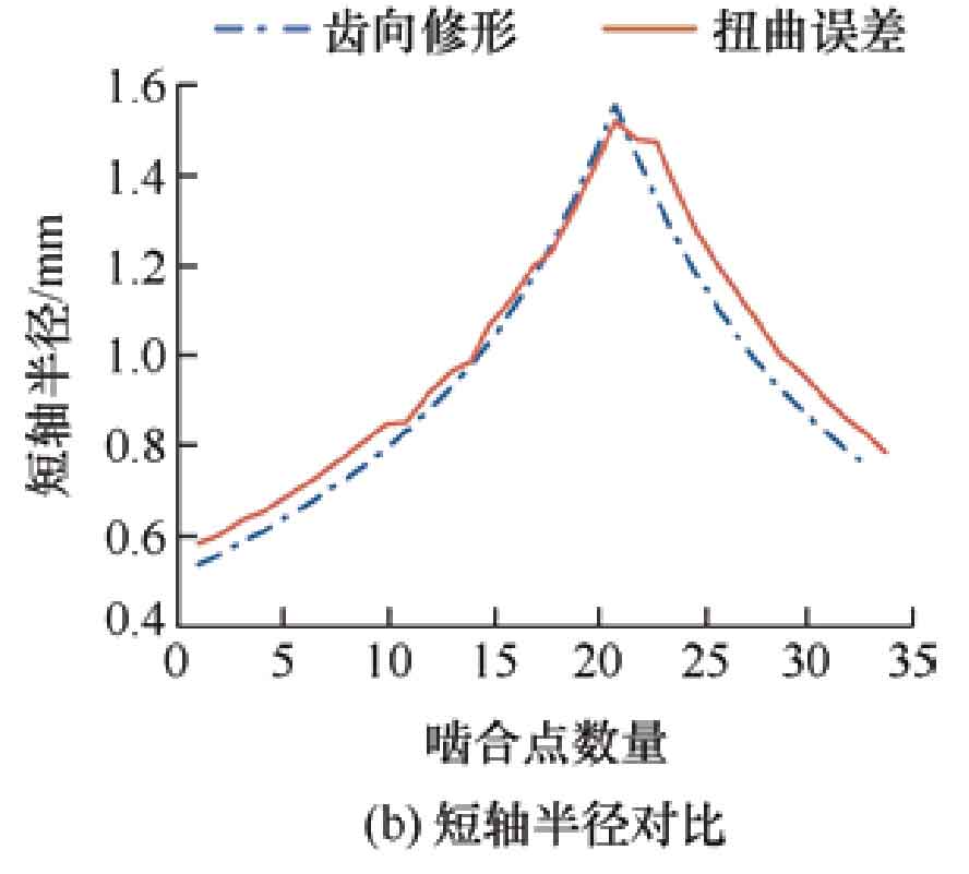
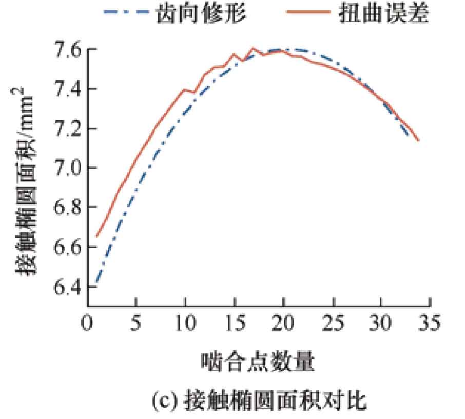
When the modification amount of the helical gear is 30 μ When m is reached, Figure 9a shows a comparison of the major axis radii of the contact ellipse, and Figure 9b shows a comparison of the minor axis radii of the contact ellipse. From the results, it can be seen that as the meshing transmission progresses, the contact elliptical long axis of the modified tooth surface first decreases and then increases, and the short axis first increases and then decreases; The contact elliptical long and short axis radii of the twisted tooth surface show uneven changes, but the overall trend of change is the same as that of the modified tooth surface, and there is no significant change in the length and area of the contact elliptical radii of the two.
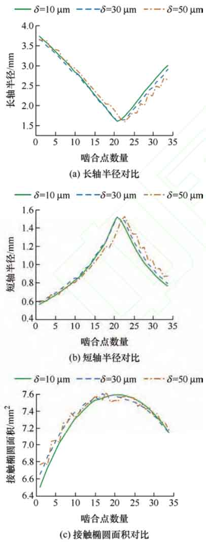
Figure 10 shows the contact ellipse length, short axis radius, and area corresponding to different modification amounts of helical gears, with modification amounts of 10, respectively μ m. 30 μ m. 50 μ M. When the shaping amount is 10 μ At m, the radius of the long and short axes and the contact area change smoothly. But as the amount of shaping increases, the radius and contact ellipse area change dramatically, gradually becoming serrated.
When the modification amount of the helical gear is 30 μ m. The long and short axis radii of the contact ellipse at helix angles of 15 º, 20 º, and 25 º are shown in Figures 11a and 11b. As the helix angle increases, the curves of the long and short axis radii of the contact ellipse at the time of meshing in and out become more pronounced in a serrated shape, corresponding to the variation of the transmission error curve within the cycle. Figure 11c shows the contact ellipse area corresponding to three helix angles. The contact ellipse area affects the magnitude of contact stress. As the helix angle increases, the contact ellipse area decreases, and the smaller the contact ellipse area, the greater the contact stress.
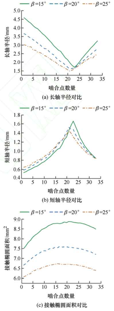
In summary, compared to the influence of the modification amount on the contact ellipse area, the size of the helix angle has a more significant impact on the contact ellipse area. Therefore, when improving the tooth surface contact stress of helical gears with twisted errors, the helix angle should be prioritized for design.

