1. Standard modified tooth surface equation
When modifying helical gears in tooth direction, the modification curve is superimposed on the helix at the indexing circle, as shown in Figure 1a. The tooth drum modification curve is shown in Figure 1b, and the relationship between the modification amount and the tooth width position is:

According to the formation principle of the modified tooth surface, the modified tooth surface equation is established by adding an additional angle. As shown in Figure 1c, the modification amount of the helical gear in the tooth width direction is calculated from the drum shaped modification curve δ n. Change the position of the helical gear profile according to the size of the modification amount at each section. The additional rotation of the helical gear end face profile can be expressed as:
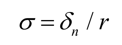
In the formula, r is the radius of the indexing circle of the helical gear.
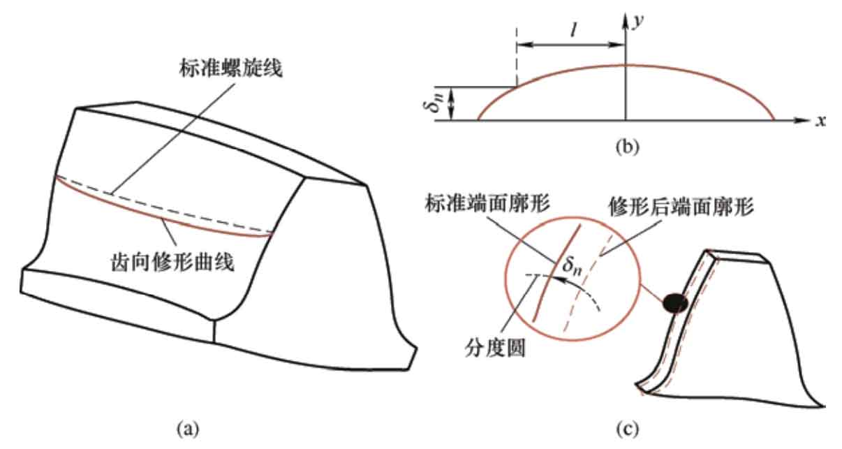
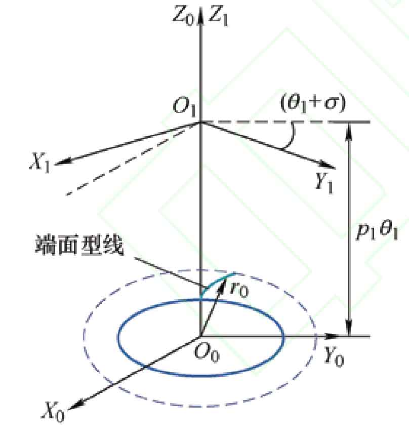
Figure 2 shows the coordinate system for the spiral motion of the involute of the modified driving wheel. S0 (O0-X0, Y0, Z0) is a fixed coordinate system, and the involute r0 undergoes a spiral motion around Z0, with a rotation angle around the Z0 axis θ At this point, the surface formed by the involute of the helical gear is a standard helical surface. But due to the presence of additional motion, the angle of rotation around the Z0 axis becomes θ 1+ σ, S1 (O1-X1, Y1, Z1) is the coordinate system after the involute undergoes a spiral motion. The coordinate transformation matrix from S0 to S1 is:
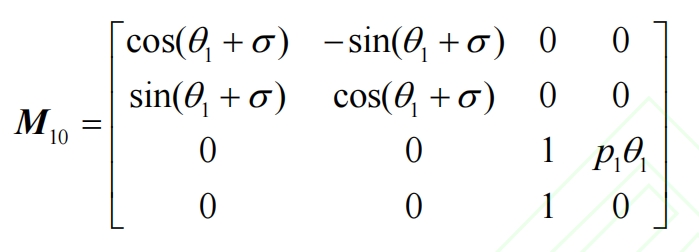
In the formula, p1 is the helix parameter.
Similarly, the coordinate transformation matrix for spiral motion of an unmodified driven wheel involute is:
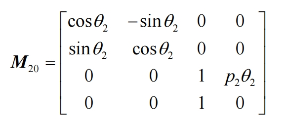
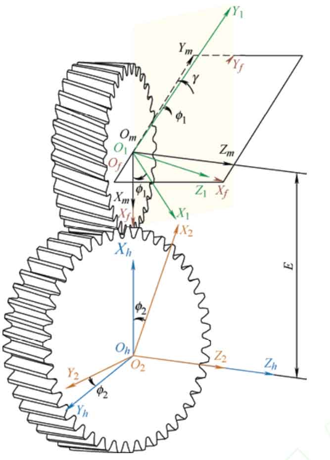
Figure 3 shows the meshing coordinate system of a staggered helical gear pair, with the driving wheel being a tooth profile modified helical gear and the driven wheel being a standard helical gear. Sf (Of-Xf, Yf, Zf) and Sh (Oh-Xh, Yh, Zh) are fixed on the frame, S1 (O1-X1, Y1, Z1) and S2 (O2-X2, Y2, Z2) are rigidly connected to two helical gears, respectively, with Sm (Om-Xm, Ym, Zm) as the auxiliary coordinate system. During the meshing process, the two helical gears rotate around the Z1 and Z2 axes respectively, and the intersection angle of Z1 and Z2 axes is γ,φ 1 and φ 2 are the instantaneous angles of the driving wheel and the driven wheel, respectively. The tooth surface equations and unit normal vectors of the driving and driven wheels in the coordinate system Sf can be represented through the following coordinate transformation.
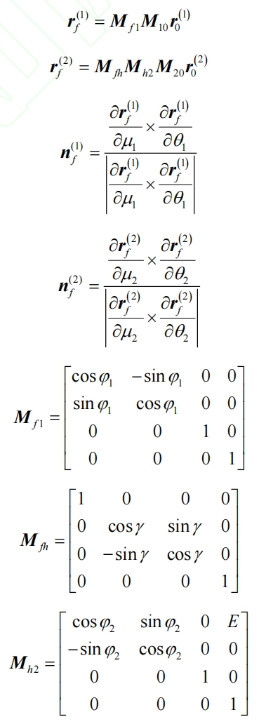
In the equation, r (i) 0 is the involute equation, μ I is the angle of involute rotation, θ I is the angle at which the involute of the helical gear rotates around the axis, where i is 1 or 2, representing the driving or driven wheel. Mf1 is the coordinate transformation matrix from coordinate system S1 to Sf, Mh2 is the coordinate transformation matrix from coordinate system S2 to Sh, and Mfh is the coordinate transformation matrix from coordinate system Sh to Sf.
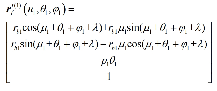
The tooth surface equation of the helical gear tooth profile modification drum tooth driving wheel is:
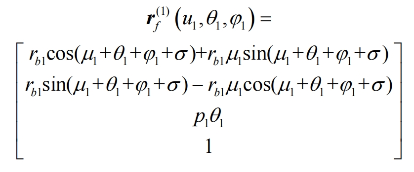
In the formula, rb1 is the radius of the base circle of the driving wheel.
2. Modified tooth surface equation with distortion error
When the worm wheel is continuously extended to grind helical gears, a series of parallel contact marks are formed on the tooth surface, and there is an angle between the contact marks and the end section of the helical gear β b. All contact marks form the machined tooth surface, as shown in Figure 4a. Due to the presence of the included angle, the end section is formed by different contact traces, as shown in Figure 4a, L1 and L2 are the contact traces corresponding to the grinding end section tooth top and tooth root, respectively. However, each contact trace has different tooth profile modifications at the indexing circle, resulting in distortion of the tooth surface, as shown in Figure 4b.
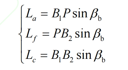
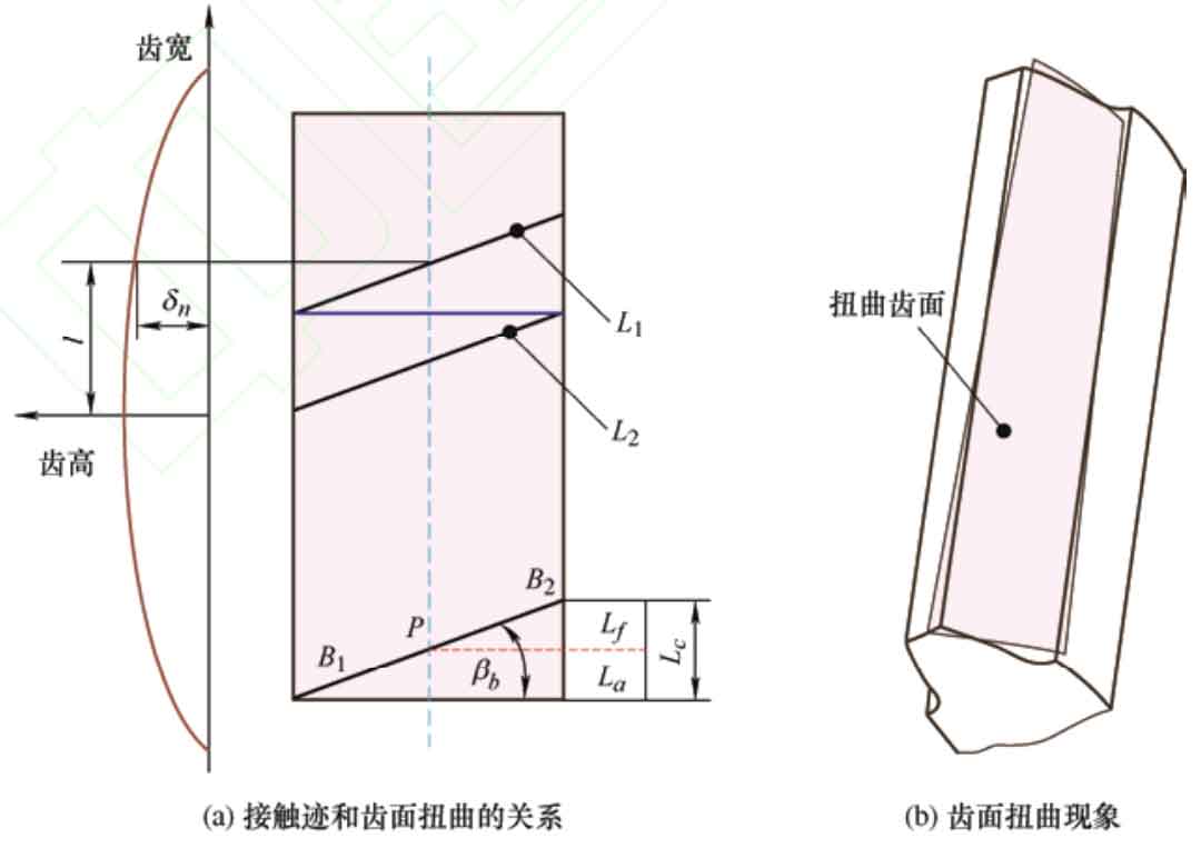
In Figure 4a, B1B2 represents the length of the meshing line between the worm grinding wheel and the helical gear, where B1P is the length of the meshing line from the contact point of the indexing circle to the contact point of the tooth top circle, and PB2 is the length of the meshing line from the contact point of the indexing circle to the contact point of the tooth root circle. The length of the meshing line along the tooth width direction is:
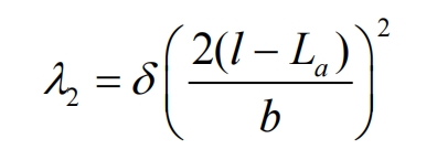
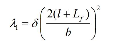
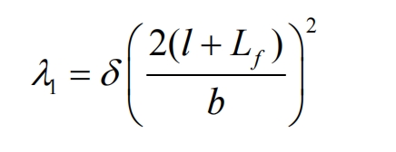
When calculating the amount of tooth profile modification for twisted tooth surfaces, dividing it into: λ 1 and λ Two part calculation:

In the formula, δ Is the total tooth profile modification amount, b is the tooth width of the helical gear, and l is the modification amount δ The distance from n to the center of tooth width. The additional turning angle of the twisted tooth surface is:
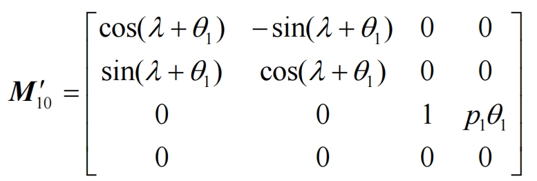
The angle at which an involute performs a spiral motion is θ 1+ λ, Coordinate transformation matrix.
The position vector of the drum tooth driving wheel with distortion error in the fixed coordinate system Sf of the helical gear is:
