
In my investigation of an engine reducer that failed during a test qualification campaign, I concentrated on a pinion gear whose working tooth surface developed an inverted triangular damage pattern. The pinion gear is the driving gear in the main transmission chain of the reducer. The reducer is an independent unit mounted at the front of a turboprop engine, and it drives the propeller together with the aircraft accessories. The main transmission gears carry very high loads, and the pinion gear must therefore satisfy demanding high-temperature performance requirements. In my analysis, the pinion gear was made of 10CrNi2Mo3Cu2V steel, carburized and quenched, with a surface hardness greater than 60 HRC, a core hardness between 33 and 41 HRC, and an effective case depth between 0.6 and 0.9 mm. I used macro and micro observation, metallographic examination, hardness testing, and simulation calculation to determine the nature and cause of the tooth surface damage. The results showed that the inverted triangular damage on the pinion gear was contact fatigue spalling. The spalling pit originated from a micro-pitting zone located below the main damaged area. The cause of the spalling was excessive local contact stress caused by a small profile modification amount and a small tooth tip chamfer on the driven gear. The local contact stress exceeded the contact fatigue limit of the pinion gear material. After I proposed and implemented improvement measures, namely increasing the driven gear profile modification amount and standardizing the tooth tip chamfering process while improving machining quality, the reducer passed the qualification examination smoothly.
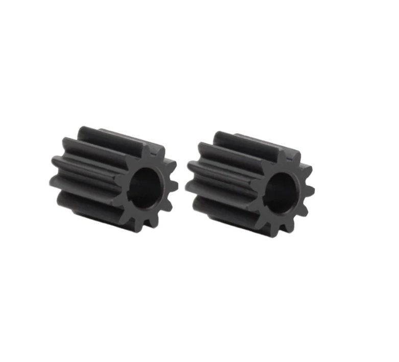
The pinion gear is a critical component in the reducer, and its failure directly affects the reliability and service life of the entire transmission system. In my examination, the failed pinion gear showed multiple teeth on the left-hand helical side with the same type of damage. The damage appeared on the working face, had an inverted triangular shape, and in some locations had already produced a visible fracture block at the tooth tip. The two journals on either side of the pinion gear showed slight fretting wear marks, but no other abnormal features were observed. The damage was not random; it repeated on several teeth of the same pinion gear, which suggested a systematic cause related to the gear pair geometry, load distribution, or manufacturing deviation rather than an isolated material defect.
Under stereomicroscopic observation, the damaged region on the pinion gear was located approximately in the middle of the tooth length direction. In the tooth height direction, the damage was roughly one-third of the tooth height away from the root. The top of the inverted triangle was about 3.5 mm from the root and extended toward the tooth tip. A linear heavy contact feature was present near the root, essentially in the middle of the tooth length direction, and it was located below the inverted triangular damage. This heavy contact mark was an important clue because it indicated that the contact pattern had shifted toward the root region of the pinion gear. When I examined the working face under a scanning electron microscope, the spalling zone showed a clear inverted triangular morphology with a definite directionality. Based on the spalling direction, I concluded that the spalling initiated from the micro-pitting zone along the lower edge of the inverted triangle and then propagated toward the tooth tip. Below the starting position of the inverted triangular spalling pit, there was a micro-pitting zone approximately 1.89 mm wide. Around the source zone of the spalling, similar but more pronounced micro-pitting features were visible, and in severe locations these had already developed into small spalling pits. In the source zone, clear heavy contact marks from gear meshing were visible. Inside the inverted triangular spalling pit, distinct fatigue striations were observed. These observations confirmed that the damage was a fatigue-driven process, not a single overload fracture or an isolated manufacturing defect.
To understand the damage mechanism more precisely, I prepared metallographic specimens from the damaged tooth at the spalling location and from a normal tooth at the middle position. After mounting and polishing, I examined the microstructure, case depth, and hardness. In the polished condition, near the starting position of the spalling on the tooth with the tip fracture, I observed a crack propagating at approximately 30° to the tooth surface. The crack initiation region showed obvious spalling and material loss, but no significant non-metallic inclusions were found at the source. After etching with a 4% nitric acid alcohol solution, the carburized layer on the tooth surface was clearly visible and relatively uniform. The carburized layer microstructure consisted of hidden needle martensite, a small amount of granular carbides, and a small amount of retained austenite. The core matrix was tempered martensite. The gear microstructure showed no abnormalities, and there was no significant difference between the damaged tooth and the normal teeth. This indicated that the material itself, including its heat treatment condition, was not the primary cause of the pinion gear failure.
Hardness testing was performed using the microhardness gradient method on the metallographic specimens. The effective case depth was determined at 550 HV with a test load of 500 g. The subsurface Vickers hardness was converted to Rockwell hardness according to the relevant standard. The results are summarized in Table 1. The effective case depth at all measured positions on the pinion gear satisfied the design requirement of 0.6 to 0.9 mm. The subsurface hardness ranged from 61.0 to 63.5 HRC, which met the design requirement of at least 60 HRC. The hardness gradient from the carburized surface layer to the core decreased gradually and consistently. The core hardness was approximately 39 to 40 HRC, which also satisfied the design requirement of 33 to 41 HRC. Therefore, the hardness of the damaged pinion gear was not abnormal, and it did not differ significantly from that of the normal teeth. This further supported the conclusion that the failure was related to contact stress rather than to material hardness or case depth deficiency.
| Zone | Damaged tooth case depth / mm | Damaged tooth subsurface hardness / HRC | Normal tooth case depth / mm | Normal tooth subsurface hardness / HRC |
|---|---|---|---|---|
| Working face | 0.897 | 63.5 | 0.881 | 63.0 |
| Non-working face | 0.883 | 63.0 | 0.898 | 61.0 |
| Dedendum | 0.807 | 61.0 | 0.753 | 61.0 |
I rechecked the tooth profile modification conditions of the pinion gear and the driven gear. The modification parameters of the pinion gear were within the design requirements. However, the profile modification amount of the driven gear was too small, and some measured values were out of tolerance. The minimum measured value was only 9.4 μm, which did not satisfy the design requirement of 10 to 20 μm. This was a significant finding because the profile modification amount directly controls the contact pattern and the distribution of contact stress along the tooth profile. When the modification amount is insufficient, the contact pattern can shift toward the root or tip, creating local stress concentrations. I also found that the design drawing required the driven gear tooth tip chamfer or round to be 0.4 to 0.5 mm. In the actual measured matched driven gear, the tooth tip was in a chamfered state, but all measured chamfer values were too small, ranging from 0.10 to 0.19 mm. This did not meet the design requirement. Moreover, the chamfer had been manually ground, so it was irregular and prone to local sharp edges. These two deviations, namely the insufficient profile modification and the undersized and irregular tip chamfer, became the central focus of my root cause analysis.
Based on the measured modification parameters and load conditions of the pinion gear and the driven gear, I established a simulation model of the reducer using Romax software. The model was used to analyze the contact pattern and contact stress of the main transmission gear pair under the actual measured parameters. The simulation showed that the heavy contact zone on the pinion gear shifted downward and extended toward the root. This matched the heavy contact feature observed on the failed pinion gear. I then performed a parametric study on different tooth tip radii of the driven gear. The results showed that when the driven gear tooth tip radius R was 0.1 mm, the maximum stress at the tooth tip reached 2113 MPa, which was 130.3% higher than the tooth surface stress. This value clearly exceeded the ultimate strength of the gear material. When the tooth tip radius R increased to 0.4 to 0.5 mm, the maximum stress moved from the tooth tip to the middle of the tooth surface. When the tooth tip radius R increased to 0.5 mm, the maximum stress on the tooth surface was 851 MPa, and the maximum stress at the tooth tip was 779 MPa. The overall contact stress was then normal and did not exceed the fatigue limit of the gear material. The simulation results indicated that as the driven gear tooth tip radius increased, the tooth tip stress decreased, the maximum stress shifted to the tooth surface, and the boundary and local stresses near the root contact mark of the pinion gear decreased as well. This provided strong numerical evidence that the small tip chamfer and small profile modification were responsible for the excessive local contact stress on the pinion gear.
| Driven gear tip radius R / mm | Maximum stress location | Maximum contact stress / MPa | Relative increase over tooth surface stress / % | Comparison with material fatigue limit |
|---|---|---|---|---|
| 0.1 | Tooth tip | 2113 | 130.3 | Exceeds limit |
| 0.4 | Tooth surface middle | 1025 | — | Below limit |
| 0.5 | Tooth surface middle | 851 | — | Below limit |
The macro and micro examination results showed that the inverted triangular spalling pit on the pinion gear was contact fatigue spalling. It originated from the micro-pitting zone near the root, where heavy contact marks were present. Combining the measured gear pair modification results and the simulation analysis of the driven gear tooth tip chamfer, I concluded that the small modification amount of the driven gear caused the heavy load zone of the pinion gear to extend toward the root. The small and irregular tooth tip chamfer of the driven gear caused a local contact stress increase near the root contact boundary of the pinion gear. The high stress exceeded the fatigue limit of the pinion gear material, causing local micro-pitting in the heavy contact zone near the root. Under repeated meshing cycles, the micro-pitting further propagated and eventually formed a large inverted triangular spalling pit on the pinion gear tooth surface, followed by fracture at the tooth tip. Therefore, the inverted triangular spalling pit on the pinion gear originated from micro-pitting in the heavy contact zone near the root. Its nature was fatigue, and it was caused by excessive local stress in the heavy contact zone near the root due to the small gear pair modification amount and the small and irregular driven gear tooth tip chamfer.
According to rough surface contact theory, when the reducer gear pair surfaces are in actual contact, the real contact area is much smaller than the nominal macroscopic contact area. Contact occurs only on a small number of asperities on the working tooth surface. Because of the sharp edge of the driven gear tooth tip chamfer, the radius of curvature becomes smaller, and the nominal contact stress near the root becomes larger. The number of asperities actually in contact is further reduced, and the asperities near the heavy contact region at the pinion gear root must carry extremely high Hertzian stress. This stress exceeds the fatigue limit of the pinion gear material 10CrNi2Mo3Cu2V. When the pinion gear meshes with the driven gear, the engagement starts from the near-root region of the pinion gear and the tooth tip of the driven gear. Below the pitch circle of the pinion gear, the motion is sliding plus rolling, with the sliding direction toward the root and the rolling direction toward the tip. Therefore, a relatively large sliding friction force exists near the pinion gear root, and this friction force generates shear stress on the surface asperities. Under the combined action of Hertzian and shear cyclic stresses, the asperities on the pinion gear tooth surface undergo plastic deformation. With the accumulation and flow of plastic deformation, tensile residual stress is generated on the asperities. As the number of cycles increases, fatigue cracks begin to form, producing early micro-pitting. When the pinion gear and driven gear tooth surfaces are in contact, lubricating oil is present between the two contact surfaces, and the stress on the tooth surface is transmitted through the oil film. Because the compressive stress, that is, the contact stress, at a position about one-third of the tooth height from the root of the pinion gear is very high, the oil pressure is also high. After early micro-pitting pits form on the tooth surface, local stress concentration occurs around the micro-pitting pits, and high-pressure oil is stored in the already formed micro-pits. Due to the simultaneous rolling and sliding below the pitch circle of the pinion gear, the high oil pressure further creates very high tensile stress at the tips of the micro-pits or micro-cracks. Under repeated meshing contact between the pinion gear and the driven gear, the cracks on the pinion gear tooth surface propagate more rapidly, and material is peeled from the tooth surface, forming an inverted triangular fan-shaped spalling pit. This mechanism of oil acting on the crack tip is called the hydraulic pressure propagation effect, or HPP effect. Because local stress concentration and the HPP effect exist simultaneously, an inverted triangular spalling pit is generally produced on the tooth surface. There are certain differences between ordinary fatigue spalling and spalling and crack propagation under the HPP effect in terms of subsequent propagation direction and macroscopic shape.
Due to repeated meshing contact between the pinion gear and the driven gear, the pinion gear tooth surface experiences cyclic tensile stress during repeated meshing. This causes the crack in the spalling zone to propagate toward the tooth tip. At the same time, because the tooth tip has a relatively deep carburized layer and higher brittleness, the tooth tip is prone to forming a fracture block. This can be regarded as secondary damage caused by crack propagation from the triangular spalling zone. My analysis therefore treated the inverted triangular spalling as the primary contact fatigue damage and the tooth tip fracture as a secondary consequence of crack propagation and local brittleness.
To describe the contact stress quantitatively, I used the standard Hertzian contact stress formula for involute gears. The maximum contact stress can be expressed as
$$ \sigma_H = Z_E \sqrt{\frac{K F_t}{b d_1} \frac{u+1}{u}} $$
where \(Z_E\) is the elastic coefficient, \(K\) is the load factor, \(F_t\) is the tangential force, \(b\) is the effective face width, \(d_1\) is the pitch diameter of the pinion gear, and \(u\) is the gear ratio. The elastic coefficient is given by
$$ Z_E = \sqrt{\frac{1}{\pi \left( \frac{1-\nu_1^2}{E_1} + \frac{1-\nu_2^2}{E_2} \right)}} $$
where \(\nu_1\) and \(\nu_2\) are the Poisson ratios, and \(E_1\) and \(E_2\) are the elastic moduli of the pinion gear and the driven gear, respectively. The tangential force is related to the normal force by
$$ F_n = \frac{F_t}{\cos \alpha_n \cos \beta} $$
where \(\alpha_n\) is the normal pressure angle and \(\beta\) is the helix angle. The contact stress along the tooth profile can be modified by the profile modification amount. In a simplified form, the local contact stress can be written as
$$ \sigma_H(x) = \sigma_{H0} \sqrt{\frac{1}{1 + \left( \frac{x}{a} \right)^2}} $$
where \(x\) is the distance from the theoretical contact center, \(a\) is the contact half-width, and \(\sigma_{H0}\) is the nominal maximum contact stress. When the profile modification is insufficient, the effective contact width shifts, and the maximum stress moves toward the root or tip. For asperity-level contact, the real contact area \(A_r\) is related to the normal load \(F_N\) and the mean contact pressure \(p_m\) by
$$ A_r = \frac{F_N}{p_m} $$
The asperity contact pressure \(p_{asp}\) is then
$$ p_{asp} = \frac{F_{asp}}{A_{asp}} $$
where \(F_{asp}\) is the load carried by the asperities and \(A_{asp}\) is the asperity contact area. Because the real contact area is much smaller than the nominal area, the asperity contact pressure can greatly exceed the nominal Hertzian stress. This explains why micro-pitting can initiate even when the nominal contact stress appears to be within the material limit. The stress intensity factor at a crack tip under the HPP effect can be estimated as
$$ K_I = \sigma \sqrt{\pi a} $$
where \(\sigma\) is the applied tensile stress and \(a\) is the crack length. When high-pressure oil enters the crack, the effective tensile stress at the crack tip increases, and the stress intensity factor increases accordingly. This accelerates crack propagation and leads to the formation of the spalling pit. The fatigue life under contact loading can be approximated by a power-law relationship:
$$ N = \left( \frac{\sigma_{-1}}{\sigma_H} \right)^m C $$
where \(N\) is the number of cycles to failure, \(\sigma_{-1}\) is the fatigue limit, \(\sigma_H\) is the contact stress, \(m\) is the fatigue exponent, and \(C\) is a material constant. The safety factor with respect to contact fatigue is
$$ S_H = \frac{\sigma_{H,\lim}}{\sigma_H} $$
For the pinion gear, the contact fatigue limit \(\sigma_{H,\lim}\) must be greater than the maximum local contact stress. In the failed condition, the simulation showed that the local stress reached 2113 MPa, which exceeded the material limit. In the improved condition, the maximum stress decreased to 851 to 1025 MPa, which was below the limit. These formulas and calculations support the conclusion that the failure was driven by local contact stress exceeding the material fatigue limit.
| Parameter | Symbol | Value or range | Unit |
|---|---|---|---|
| Pinion gear material | — | 10CrNi2Mo3Cu2V | — |
| Surface hardness | — | > 60 | HRC |
| Core hardness | — | 33–41 | HRC |
| Effective case depth | — | 0.6–0.9 | mm |
| Driven gear profile modification requirement | — | 10–20 | μm |
| Measured minimum profile modification | — | 9.4 | μm |
| Driven gear tip chamfer requirement | R | 0.4–0.5 | mm |
| Measured tip chamfer range | R | 0.10–0.19 | mm |
| Maximum stress with R = 0.1 mm | \(\sigma_{H,\max}\) | 2113 | MPa |
| Maximum stress with R = 0.4 mm after improvement | \(\sigma_{H,\max}\) | 1025 | MPa |
| Maximum stress with R = 0.5 mm | \(\sigma_{H,\max}\) | 851 | MPa |
I also considered the influence of the contact pattern on the pinion gear. When the driven gear profile modification amount is too small, the contact pattern on the pinion gear shifts toward the root. This creates a heavy contact zone below the pitch line, where sliding and rolling combine. In this region, the sliding velocity is relatively high, and the friction force is significant. The friction force adds a shear component to the contact stress and promotes asperity plastic deformation. When the driven gear tooth tip chamfer is too small, the contact at the beginning of engagement occurs closer to a sharp edge, which reduces the local radius of curvature and raises the local contact stress. The combination of these two effects produces a stress concentration at the lower boundary of the heavy contact zone on the pinion gear. This stress concentration is the origin of the micro-pitting and subsequent spalling. The inverted triangular shape of the spalling pit is a consequence of the contact stress distribution and the direction of crack propagation. The lower edge of the triangle corresponds to the micro-pitting origin near the root, and the apex of the triangle points toward the tooth tip because the crack propagates in the direction of the sliding and tensile stress. The fatigue striations observed inside the pit confirm that the failure was progressive and cyclic, not instantaneous.
The metallographic examination also revealed a crack at approximately 30° to the tooth surface near the spalling initiation. This crack angle is typical of contact fatigue cracks that initiate at the surface or near the surface and propagate under mixed mode loading. The absence of non-metallic inclusions at the source zone rules out inclusion-initiated fatigue. The uniform carburized layer and the absence of abnormal microstructure rule out heat treatment defects. The hardness results rule out insufficient surface hardness or shallow case depth. Therefore, the only remaining significant factor is the contact stress concentration caused by the gear pair geometry and manufacturing deviations. This is a strong conclusion because it is supported by the simulation results, the measured modification deviations, and the observed damage morphology.
Based on the cause and mechanism analysis of the inverted triangular spalling damage on the pinion gear, I proposed that appropriately increasing the driven gear profile modification amount and its tooth tip radius could improve the gear pair contact pattern and avoid local stresses exceeding the material fatigue limit. The improvement measures were as follows. First, the gear pair contact pattern was adjusted by changing the driven gear profile modification amount from 10 to 20 μm to 18 to 25 μm. This was intended to shift the pinion gear tooth surface contact pattern toward the tooth tip and the driven gear tooth surface contact pattern toward the root. Second, the tooth tip chamfering process was standardized to improve machining quality, ensuring that the tooth tip chamfer R remained stable at 0.4 to 0.5 mm. A tooth tip chamfer inspection requirement was also established. These measures were implemented in the manufacturing process.
| Improvement item | Before improvement | After improvement | Purpose |
|---|---|---|---|
| Driven gear profile modification amount | 10–20 μm, minimum 9.4 μm | 18–25 μm | Shift contact pattern away from pinion gear root |
| Driven gear tooth tip chamfer | 0.10–0.19 mm, irregular manual grinding | 0.4–0.5 mm, regular process | Reduce local stress concentration at tooth tip and root boundary |
| Contact pattern on pinion gear | Heavy contact zone extended toward root | Heavy contact zone moved upward | Distribute contact stress more uniformly |
| Maximum contact stress | 2113 MPa at R = 0.1 mm | 1025 MPa at R = 0.4 mm; 851 MPa at R = 0.5 mm | Keep stress below material fatigue limit |
| Validation test | Failure during qualification | 160 h cumulative operation, normal contact pattern | Confirm effectiveness of improvement |
After implementing the improvement measures, I used Romax software again to simulate the contact pattern of the improved gear pair. The results showed that the lower boundary of the heavy contact zone on the pinion gear moved upward. When the driven gear tooth tip radius R was 0.4 mm, the maximum stress was located at the middle of the tooth surface, and the maximum stress was 1025 MPa, which did not exceed the fatigue limit of the material. This was a substantial reduction from the 2113 MPa observed in the failed condition. The stress reduction was approximately 51.5% at the maximum stress location. When R was 0.5 mm, the maximum stress decreased further to 851 MPa. These simulation results demonstrated that the improved geometry effectively reduced the local contact stress and eliminated the stress concentration that had caused the micro-pitting and spalling.
The improved reducer was assembled and subjected to a series of tests equivalent to the failed condition. After 160 hours of cumulative operation, the reducer was disassembled and inspected. The working face of the pinion gear showed a normal contact pattern. There was no obvious heavy contact zone near the root, no local micro-pitting, and no inverted triangular spalling or other abnormal conditions. This test result confirmed that increasing the driven gear tooth tip radius and the profile modification amount to improve the gear pair contact pattern was feasible and effective. The pinion gear successfully completed the test without recurrence of the contact fatigue spalling. This was a strong validation of my root cause analysis and the proposed corrective actions.
In my assessment, the failure sequence of the pinion gear can be summarized as follows. First, the driven gear profile modification amount was too small, and the driven gear tooth tip chamfer was too small and irregular. Second, the contact pattern on the pinion gear shifted toward the root, creating a heavy contact zone near the root. Third, the local contact stress at the lower boundary of the heavy contact zone exceeded the contact fatigue limit of the pinion gear material. Fourth, micro-pitting initiated in the heavy contact zone near the root. Fifth, under repeated meshing cycles, the micro-pitting developed into surface cracks. Sixth, high-pressure oil entered the cracks and produced the HPP effect, accelerating crack propagation. Seventh, the cracks propagated toward the tooth tip, forming an inverted triangular spalling pit. Eighth, the tooth tip, which had a deep and relatively brittle carburized layer, fractured as a secondary damage. Ninth, the pinion gear lost its required surface integrity and could no longer reliably transmit power. The root cause was therefore a design and manufacturing deviation in the driven gear, not a material defect in the pinion gear.
The contact fatigue process can be further described by the relationship between the contact stress and the number of cycles. In the failed condition, the local stress \(\sigma_H\) was greater than the material contact fatigue limit \(\sigma_{H,\lim}\). The fatigue life \(N\) was therefore finite and relatively short. In the improved condition, \(\sigma_H\) was reduced below \(\sigma_{H,\lim}\), and the safety factor \(S_H\) was greater than the required minimum. The safety factor can be written as
$$ S_H = \frac{\sigma_{H,\lim}}{\sigma_H} $$
For the failed condition, using the simulation result of 2113 MPa, the safety factor was less than 1. For the improved condition, using the simulation result of 1025 MPa, the safety factor was greater than 1. This quantitative comparison explains why the pinion gear failed in the original configuration and why it survived after the improvement. The exact material fatigue limit was not stated in my source information, but the simulation comparison clearly showed that the original stress exceeded the material limit and the improved stress did not.
I also noted that the micro-pitting width below the spalling pit was approximately 1.89 mm. This width represents the zone where asperity contact and surface fatigue were most severe. The micro-pitting zone acted as the initiation site for the larger spalling pit. The presence of fatigue striations inside the spalling pit indicated that the crack propagated in a cyclic manner. The heavy contact marks in the source zone indicated that the contact pressure was locally elevated. The inverted triangular shape indicated that the crack propagation was influenced by the contact stress gradient and the sliding direction. The tooth tip fracture indicated that the crack eventually reached the tip region, where the combination of bending stress and brittleness caused a block of material to separate. All these observations are consistent with a contact fatigue failure driven by excessive local stress.
In terms of gear design, the profile modification amount is a critical parameter for controlling the contact pattern and reducing stress concentration at the tooth tip and root. If the modification amount is too small, the contact pattern may extend to the root or tip, causing edge contact and high local stress. If the modification amount is too large, the contact area may be reduced, and the load per unit width may increase. Therefore, the modification amount must be optimized for the specific load and geometry. In this case, the original requirement of 10 to 20 μm was not sufficient to prevent root contact under the actual load and manufacturing deviations. Increasing it to 18 to 25 μm shifted the contact pattern to a more favorable position. Similarly, the tooth tip chamfer is important for avoiding sharp edge contact at the beginning of engagement. A small chamfer can produce a sharp edge that concentrates stress. A properly sized chamfer of 0.4 to 0.5 mm distributes the contact and reduces the peak stress. The manual and irregular chamfer in the original parts was particularly detrimental because it could produce local sharp edges and inconsistent contact conditions from tooth to tooth. Standardizing the chamfering process ensured consistent geometry and stress distribution.
The simulation results also showed that the maximum stress location moved from the tooth tip to the tooth surface middle when the tip radius increased. This is a beneficial change because the tooth surface middle has a more favorable stress state and a larger contact area. The root region of the pinion gear is particularly vulnerable because it experiences sliding plus rolling and high friction. By moving the heavy contact zone away from the root, the improved design reduced the risk of micro-pitting and spalling. The stress reduction from 2113 MPa to 1025 MPa or 851 MPa was significant. The improved stress levels were below the material fatigue limit, providing a sufficient safety margin. The 160-hour validation test confirmed that the improved pinion gear could operate without contact fatigue damage.
In my conclusion, the inverted triangular damage on the pinion gear tooth surface was contact fatigue spalling. The spalling pit originated from the micro-pitting zone near the root and extended toward the tooth tip. The small gear pair modification amount and the small and irregular driven gear tooth tip chamfer caused excessive local contact stress, which exceeded the contact fatigue limit of the pinion gear material. This was the main cause of the tooth surface fatigue spalling. By increasing the driven gear profile modification amount and standardizing the tooth tip chamfer while improving machining quality, the reducer passed the qualification examination. The pinion gear no longer developed the inverted triangular spalling damage. These findings are relevant to the design, manufacturing, and failure analysis of similar pinion gears in engine reducers and other high-load gear transmissions.
| Failure stage | Observation or mechanism | Key parameter | Result |
|---|---|---|---|
| Initial contact | Heavy contact zone near pinion gear root | Profile modification too small | Contact pattern shifted toward root |
| Local stress concentration | Sharp driven gear tooth tip chamfer | R = 0.10–0.19 mm | Maximum stress 2113 MPa |
| Micro-pitting initiation | Asperity contact and plastic deformation | Real contact area much smaller than nominal | Micro-pitting zone width 1.89 mm |
| Crack propagation | Cyclic shear and tensile stress | Fatigue striations observed | Surface cracks developed |
| HPP effect | High-pressure oil in micro-pits | Stress intensity factor increased | Rapid crack growth |
| Spalling | Inverted triangular pit | Crack propagated toward tip | Material peeled from pinion gear |
| Secondary damage | Tooth tip fracture | Deep carburized layer, brittleness | Tip block separated |
| Improvement | Increased modification and chamfer | Modification 18–25 μm, R = 0.4–0.5 mm | Maximum stress 851–1025 MPa |
| Validation | 160 h operation | Normal contact pattern | No spalling or micro-pitting |
I also summarize the key numerical values in Table 5 for clarity. These values are drawn from the hardness tests, modification measurements, and simulation results. The table shows the contrast between the failed condition and the improved condition. The failed condition had a small profile modification, a small tip chamfer, and a high maximum stress. The improved condition had a larger profile modification, a properly sized tip chamfer, and a lower maximum stress. The validation test confirmed the improvement.
| Quantity | Failed condition | Improved condition | Unit |
|---|---|---|---|
| Driven gear profile modification | 9.4–20 | 18–25 | μm |
| Driven gear tip chamfer R | 0.10–0.19 | 0.4–0.5 | mm |
| Pinion gear maximum contact stress | 2113 | 851–1025 | MPa |
| Safety factor against contact fatigue | < 1 | > 1 | — |
| Micro-pitting zone width | 1.89 | Not observed | mm |
| Spalling shape | Inverted triangle | None | — |
| Tooth tip fracture | Present | Absent | — |
| Validation duration | Failed during qualification | 160 | h |
In my final assessment, the pinion gear failure was a classic example of contact fatigue caused by an unfavorable contact pattern and local stress concentration. The pinion gear material and heat treatment were within specification. The failure was not caused by inclusions, carburizing defects, or insufficient hardness. The failure was caused by the driven gear profile modification being too small and the driven gear tooth tip chamfer being too small and irregular. These deviations produced a heavy contact zone near the pinion gear root and a local stress that exceeded the material fatigue limit. The micro-pitting that formed in this zone acted as the initiation site for the inverted triangular spalling pit. The HPP effect contributed to rapid crack propagation. The tooth tip fracture was a secondary consequence. The corrective actions were effective and were validated by simulation and by a 160-hour test. The pinion gear then operated normally. This experience reinforces the importance of controlling profile modification and tooth tip chamfer in high-load gear pairs. It also demonstrates the value of combining macro and micro observation, metallography, hardness testing, and simulation in failure analysis. The pinion gear is a critical component, and its contact fatigue performance depends on both material quality and geometric accuracy. When the geometry is not optimized, even a properly manufactured pinion gear can fail by contact fatigue. When the geometry is corrected, the pinion gear can achieve the required reliability and service life.