
In my study of corridor lifting systems, I have focused on the mechanical reliability of the rack and pinion gears that drive the seat along the guide rail. The corridor lift is a compact vertical transportation solution that can be installed along the side of a staircase without destroying the original building structure. Because it does not require a large shaft or a separate machine room, it is especially suitable for older residential buildings where low-floor residents may object to conventional elevators due to reduced lighting and ventilation. The rack and pinion gears form the core transmission pair: the pinion is mounted on the seat mechanism, while the rack is fixed inside the lower guide rail. When the pinion rotates, it climbs or descends along the rack, moving the seat upward or downward. Therefore, the strength of the rack and pinion gears directly determines whether the corridor lift can operate safely under rated load and maximum load conditions.
I began by reviewing the overall structure of the corridor lift. The system consists of two main assemblies: the seat mechanism and the guide rail mechanism. The seat mechanism is generally fixed and includes the seat, the machine box, the pinion, and the pressing devices. The guide rail mechanism is usually custom-fitted on site and includes the upper rail, the lower rail, and the rack. The seat mechanism is connected to the upper rail through pressing rollers, and the pinion meshes with the rack on the inner side of the lower rail. A paddle switch enables jog operation, and a steering handle allows the seat to rotate freely. In this arrangement, the rack and pinion gears must carry the combined weight of the seat and the passenger while maintaining stable meshing along both straight and curved sections of the staircase.
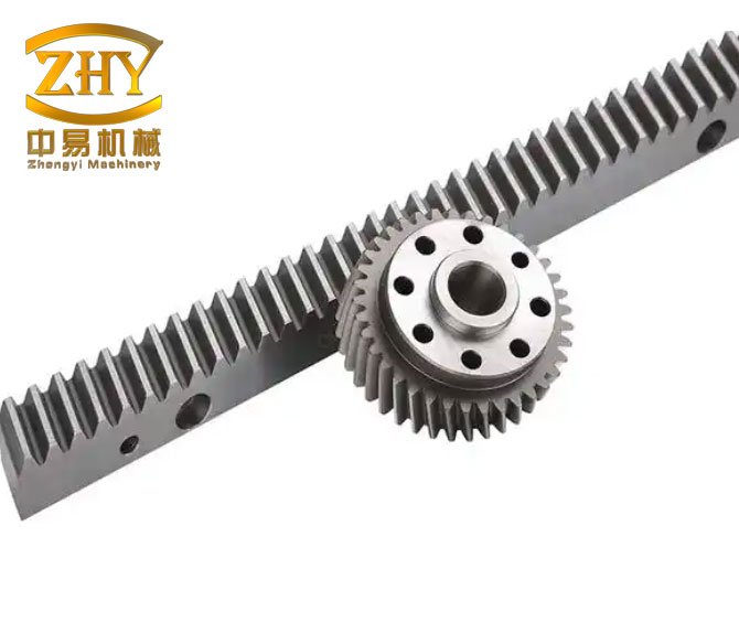
Because the rack is exposed to air and the pinion is protected by a dust cover, I treated the rack and pinion gears as an open gearing system. For open gearing, two design criteria are commonly considered: surface wear resistance and tooth root bending fatigue strength. In practice, the calculation methods for surface wear resistance are not sufficiently mature for all operating conditions, so I used tooth root bending fatigue strength as the primary design criterion. Since the pinion face width is larger than the rack face width in the corridor lift, the pinion is expected to have a higher resistance to bending fatigue failure than the rack. Therefore, I concentrated my theoretical check on the rack tooth root bending stress, while still evaluating the pinion root stress through finite element analysis.
Theoretical Strength Calculation
I assumed the pinion material to be 40Cr, quenched and tempered, with a surface hardness of HRC 48–55. The pinion module is 3.5 mm, the pressure angle is 20°, the addendum coefficient is 1, the clearance coefficient is 0.25, the number of teeth is 19, the face width is 15.5 mm, and the pitch circle diameter is 66.5 mm. The rack material is 45 steel, quenched and tempered, with a hardness of HRC 43–50. The rack module is 3.5 mm, the pressure angle is 20°, the addendum coefficient is 1, the clearance coefficient is 0.25, and the rack face width is 10 mm. These parameters are summarized in Table 1.
| Parameter | Pinion | Rack |
|---|---|---|
| Material | 40Cr, quenched and tempered | 45 steel, quenched and tempered |
| Hardness | HRC 48–55 | HRC 43–50 |
| Module, m | 3.5 mm | 3.5 mm |
| Pressure angle | 20° | 20° |
| Addendum coefficient | 1 | 1 |
| Clearance coefficient | 0.25 | 0.25 |
| Number of teeth | 19 | — |
| Face width | 15.5 mm | 10 mm |
| Pitch circle diameter, d1 | 66.5 mm | — |
For the rack tooth root bending stress, I used the following equation:
$$
\sigma_F = \frac{2 K_F T Y_{Fa} Y_{sa} Y_\varepsilon}{\phi_d m^3 z_1^2}
$$
where \(\sigma_F\) is the rack tooth root bending stress in MPa, \(K_F\) is the load factor, \(T\) is the maximum torque transmitted by the pinion in N·mm, \(Y_{Fa}\) is the tooth form factor, \(Y_{sa}\) is the stress correction factor when the load is applied at the tooth tip, \(Y_\varepsilon\) is the contact ratio factor, \(\phi_d\) is the face width factor, \(m\) is the pinion module in mm, and \(z_1\) is the number of pinion teeth. According to the gear handbook, I took \(Y_{Fa} = 2.86\) and \(Y_{sa} = 1.54\). The load factor is calculated as:
$$
K_F = K_A K_V K_{F\alpha} K_{F\beta}
$$
I selected the application factor \(K_A = 1.0\) because the corridor lift operates smoothly and uniformly. The dynamic factor \(K_V = 1.05\) corresponds to a transmission accuracy of grade 8 and a pitch line velocity of 0.1 m/s. The transverse load distribution factor \(K_{F\alpha} = 1.2\) was chosen for an 8-grade hard-tooth-surface spur gear. The face load distribution factor \(K_{F\beta} = 1.099\). Substituting these values gives:
$$
K_F = 1.0 \times 1.05 \times 1.2 \times 1.099 = 1.385
$$
The maximum torque transmitted by the pinion is calculated from the forces acting on the seat mechanism:
$$
T = \left( F_g \sin\alpha + \mu F_g \cos\alpha \right) \frac{d_1}{2}
$$
where \(F_g\) is the combined force of the seat weight and the maximum payload in N, \(\mu\) is the rolling friction coefficient between the seat and the guide rail mechanism, \(\alpha\) is the staircase inclination angle in degrees, and \(d_1\) is the pinion pitch circle diameter in mm. I assumed a seat structure weight of 100 kg, a maximum payload of 115 kg, a rated speed of 0.1 m/s, a staircase inclination angle \(\alpha = 45^\circ\), and a rolling friction coefficient \(\mu = 0.25\). The gravitational acceleration is \(9.81 \, \text{m/s}^2\). Therefore, the combined force is:
$$
F_g = (100 + 115) \times 9.81 = 2109.15 \, \text{N}
$$
Substituting into the torque equation gives:
$$
T = \left( 2109.15 \sin 45^\circ + 0.25 \times 2109.15 \cos 45^\circ \right) \frac{66.5}{2}
$$
$$
T = \left( 2109.15 \times 0.7071 + 0.25 \times 2109.15 \times 0.7071 \right) \times 33.25
$$
$$
T = \left( 1491.39 + 372.85 \right) \times 33.25 = 1864.24 \times 33.25 = 61986.07 \, \text{N·mm}
$$
The contact ratio factor is calculated as:
$$
Y_\varepsilon = 0.25 + \frac{0.75}{\varepsilon_\alpha}
$$
I used a gear contact ratio \(\varepsilon_\alpha = 1.76\), which gives:
$$
Y_\varepsilon = 0.25 + \frac{0.75}{1.76} = 0.25 + 0.4261 = 0.6761 \approx 0.68
$$
The face width factor is:
$$
\phi_d = \frac{b}{d_1}
$$
where \(b\) is the rack face width. With \(b = 10 \, \text{mm}\), I obtained:
$$
\phi_d = \frac{10}{66.5} = 0.1504 \approx 0.15
$$
Finally, substituting all values into the bending stress equation gives:
$$
\sigma_F = \frac{2 \times 1.385 \times 61986.07 \times 2.86 \times 1.54 \times 0.68}{0.15 \times 3.5^3 \times 19^2}
$$
$$
\sigma_F = \frac{2 \times 1.385 \times 61986.07 \times 2.86 \times 1.54 \times 0.68}{0.15 \times 42.875 \times 361}
$$
$$
\sigma_F = \frac{2 \times 1.385 \times 61986.07 \times 2.86 \times 1.54 \times 0.68}{2321.68}
$$
$$
\sigma_F = \frac{502984.8}{2321.68} = 221.46 \, \text{MPa}
$$
Thus, the theoretical maximum bending stress at the rack tooth root is 221.46 MPa. This value becomes the reference for validating my finite element model of the straight rack and pinion gears.
Finite Element Modeling
Because the corridor lift operates smoothly and uniformly, I did not need to consider inertial and damping effects in the static analysis. I used SolidWorks to create a parametric model of the rack and pinion gears, and then I imported the model into ANSYS Workbench for static structural analysis. The material properties are listed in Table 2. The friction coefficient between the pinion and the rack was set to 0.1.
| Component | Density (g/cm³) | Elastic Modulus (GPa) | Poisson’s Ratio |
|---|---|---|---|
| Pinion | 7.72 | 211 | 0.277 |
| Rack | 7.89 | 209 | 0.269 |
For meshing, I used tetrahedral elements. The global element size was 1 mm, and I refined the contact surfaces and tooth root regions to 0.2 mm. The mesh contained 563,697 solid elements and 823,649 nodes. This level of refinement was necessary because the tooth root is a stress concentration region, and the contact between the rack and pinion gears must be captured accurately. I applied a fixed support to the bottom of the rack, a displacement constraint to the pinion center hole so that only rotation was allowed, and the calculated torque to the pinion. The boundary conditions and loads are summarized in Table 3.
| Boundary Condition or Load | Application |
|---|---|
| Fixed support | Bottom face of the rack |
| Displacement constraint | Pinion center hole; rotation only |
| Torque | Pinion; 61,986.07 N·mm |
| Friction coefficient | Pinion–rack contact; 0.1 |
| Mesh type | Tetrahedral |
| Global element size | 1 mm |
| Local refinement | 0.2 mm at contact and tooth root |
| Number of elements | 563,697 |
| Number of nodes | 823,649 |
Straight Rack Analysis
For the straight section of the staircase, the upper and lower guide rails are fixed along a straight line. I first analyzed the straight rack and pinion gears. After solving in ANSYS Workbench, I post-processed the results to obtain the stress contours at the tooth roots of the pinion and the rack. The maximum stress at the pinion tooth root was 96.537 MPa. The maximum stress at the rack tooth root was 228.47 MPa. The theoretical value was 221.46 MPa, so the finite element result was only 3.2% higher than the theoretical calculation. This close agreement validated my loading method and modeling approach for the straight rack and pinion gears. The comparison is shown in Table 4.
| Location | Theoretical Stress (MPa) | Finite Element Stress (MPa) | Difference |
|---|---|---|---|
| Rack tooth root | 221.46 | 228.47 | +3.2% |
| Pinion tooth root | — | 96.54 | — |
If I take the yield limit of 40Cr as 500 MPa and the yield limit of 45 steel as 360 MPa, both the pinion and the rack tooth root maximum stresses are within their respective material yield limits. The rack root stress is higher than the pinion root stress, which agrees with the expectation that the pinion has a larger face width and thus greater bending fatigue resistance. In my finite element model, the stress distribution along the straight rack tooth root was relatively uniform, without severe stress concentration. This result confirms that the straight rack and pinion gears can safely transmit the rated load under the assumed conditions.
Curved Rack Analysis
At the corner of a staircase, the rack must be bent to follow the guide rail. The stress state of a curved rack is clearly different from that of a straight rack. Because there is no simple theoretical formula for evaluating the tooth root stress of a bent rack, I relied on finite element simulation using the same material properties, mesh strategy, boundary conditions, and torque as in the straight rack case. I first assumed a bending radius of 400 mm for the inner rack at the staircase corner. The simulation showed that the maximum stress at the pinion tooth root was 189.90 MPa, and the maximum stress at the rack tooth root was 355.55 MPa. Both values are significantly higher than those in the straight case. Moreover, the bent rack exhibited a stress concentration at the tooth root, whereas the straight rack showed a more uniform stress distribution.
To study the influence of different bending radii on the maximum tooth root stresses of the rack and pinion gears, I performed a parametric study. The bending radius was varied from 200 mm to 800 mm, and I also included the straight rack as a reference. The results are summarized in Table 5. For each bending radius, I extracted the maximum stress at the pinion tooth root and the maximum stress at the rack tooth root.
| Bending Radius (mm) | Pinion Tooth Root Stress (MPa) | Rack Tooth Root Stress (MPa) |
|---|---|---|
| 200 | 221.43 | 226.31 |
| 300 | 136.75 | 236.83 |
| 400 | 189.90 | 355.55 |
| 500 | 204.19 | 400.46 |
| 600 | 192.40 | 390.25 |
| 700 | 188.67 | 382.81 |
| 800 | 180.29 | 374.87 |
| Straight (∞) | 96.54 | 228.47 |
From Table 5, I observed that for a bent rack, the maximum stresses at the pinion and rack tooth roots are generally larger than those in the straight case. At a bending radius of 200 mm, the pinion tooth root stress is much larger than the straight-case stress, while the rack tooth root stress is slightly smaller than the straight-case stress. For bending radii from 300 mm to 800 mm, both the pinion and rack tooth root maximum stresses show a trend of first increasing and then decreasing. The maximum occurs at a bending radius of 500 mm. At this radius, the pinion tooth root stress reaches 204.19 MPa, which is 2.12 times the straight-case value, and the rack tooth root stress reaches 400.46 MPa, which is 1.75 times the straight-case value.
Considering the yield limits of 500 MPa for 40Cr and 360 MPa for 45 steel, the pinion tooth root maximum stress remains within the yield limit for all bending radii studied. However, the rack tooth root maximum stress exceeds the yield limit of 45 steel at several bending radii. This does not necessarily mean that the design fails, because at the staircase corner, the rack is in a horizontal running section where the torque is only about 28% of the torque in the inclined running section for a staircase inclination angle of 45°. Therefore, the actual stress level under operating conditions is still acceptable, but the result highlights the importance of considering the curved rack separately in strength verification.
I also examined the location of the maximum rack tooth root stress. At a bending radius of 200 mm, the maximum stress appeared on the inner side of the rack. At a bending radius of 400 mm, the maximum stress appeared on the outer side of the rack. This shift is related to the meshing geometry. When the bending radius is very small, the inner tooth space of the rack becomes too narrow. As the pinion moves toward the center of curvature under the applied force, it not only meshes with the tooth tips on the outer side but also meshes with the rack at the inner pitch circle. In this situation, the force on the inner pitch circle dominates, and the maximum rack tooth root stress occurs on the inner side.
As the bending radius increases, the force on the outer tooth tips gradually increases. This causes the location of the maximum rack tooth root stress to move from the inner side to the outer side. At the same time, the meshing area between the pinion and the rack increases, and the normal contact pressure also increases. However, the rate of increase in contact pressure decreases as the bending radius becomes larger. Under the combined effect of these factors, the maximum tooth root stresses of the rack and pinion gears first increase and then decrease. The location of the maximum rack tooth root stress also gradually moves from the outer side toward the middle. When the bending radius reaches 500 mm, the maximum tooth root stresses of the pinion and rack reach their peak values of 204.19 MPa and 400.46 MPa, respectively.
In engineering practice, when the bending radius is too small, interference between the rack and pinion gears can occur and affect transmission. In such cases, the rack edges must be ground to ensure smooth meshing. This is an important manufacturing consideration for curved rack and pinion gears in corridor lifts.
Discussion of Stress Ratios and Engineering Factors
To better understand the relationship between the pinion and rack stresses, I calculated the stress ratio \(R_\sigma\) as:
$$
R_\sigma = \frac{\sigma_{\text{rack}}}{\sigma_{\text{pinion}}}
$$
For the straight rack, the ratio is:
$$
R_\sigma = \frac{228.47}{96.54} = 2.37
$$
For a bending radius of 500 mm, the ratio is:
$$
R_\sigma = \frac{400.46}{204.19} = 1.96
$$
These ratios show that the rack tooth root is consistently more heavily loaded than the pinion tooth root. This is consistent with the design assumption that the pinion has a larger face width and therefore greater bending fatigue resistance. The ratio decreases at the most severe bending radius because the pinion stress increases more rapidly than the rack stress in that configuration.
I also defined a bending influence factor \(K_b\) for the rack tooth root stress as:
$$
K_b = \frac{\sigma_{\text{rack, curved}}}{\sigma_{\text{rack, straight}}}
$$
Using the straight rack stress of 228.47 MPa as the reference, I calculated the bending influence factors for different bending radii, as shown in Table 6. These factors can be used in preliminary design to estimate the curved rack stress from the straight rack theoretical value.
| Bending Radius (mm) | Rack Stress (MPa) | Bending Influence Factor, Kb |
|---|---|---|
| 200 | 226.31 | 0.99 |
| 300 | 236.83 | 1.04 |
| 400 | 355.55 | 1.56 |
| 500 | 400.46 | 1.75 |
| 600 | 390.25 | 1.71 |
| 700 | 382.81 | 1.68 |
| 800 | 374.87 | 1.64 |
| Straight (∞) | 228.47 | 1.00 |
The bending influence factor reaches its maximum at a bending radius of 500 mm. This means that if I use the straight rack theoretical stress of 221.46 MPa and multiply it by 1.75, I obtain approximately 387.6 MPa, which is close to the finite element result of 400.46 MPa. Therefore, for preliminary engineering estimates, the curved rack tooth root stress can be approximated by multiplying the straight rack theoretical stress by a bending influence factor that depends on the bending radius. For the corridor lift studied here, a conservative bending influence factor of 1.8 can be used for bending radii near 500 mm.
Material Yield Limits and Safety Considerations
The yield limits of the materials are important for evaluating whether the rack and pinion gears can safely carry the load. Table 7 summarizes the yield limits and the maximum stresses observed in my study.
| Component | Material | Yield Limit (MPa) | Maximum Stress in Straight Section (MPa) | Maximum Stress in Curved Section (MPa) |
|---|---|---|---|---|
| Pinion | 40Cr | 500 | 96.54 | 204.19 |
| Rack | 45 steel | 360 | 228.47 | 400.46 |
In the straight section, both the pinion and the rack operate well below their yield limits. The pinion has a large margin of safety, while the rack uses about 63% of its yield limit. In the curved section, the pinion stress remains below the yield limit even at the most severe bending radius of 500 mm. The rack stress, however, exceeds the yield limit of 45 steel at bending radii of 400 mm, 500 mm, 600 mm, 700 mm, and 800 mm. This indicates that the curved rack is the critical component in the rack and pinion gears. The reason the design can still be acceptable is that the torque at the staircase corner is much lower than the torque in the inclined section. For a staircase inclination angle of 45°, the horizontal running torque is about 28% of the inclined running torque. Therefore, the actual rack stress at the corner is lower than the values obtained under the full inclined-section torque. Nevertheless, I recommend that the curved rack be carefully checked under the actual corner torque and that a sufficient safety factor be applied.
To improve the strength of the curved rack, several measures can be considered. First, increasing the rack face width would reduce the bending stress, but it may also increase the weight and affect the meshing clearance. Second, using a higher-strength material for the rack, such as 40Cr or a suitable alloy steel, would increase the yield limit and improve the safety margin. Third, optimizing the bending radius to avoid the peak stress region around 500 mm could reduce the maximum stress. Fourth, grinding the rack edges at small bending radii can prevent interference and improve the contact condition. Finally, a more detailed contact analysis that includes the actual corner torque and dynamic effects could provide a more accurate assessment of the rack and pinion gears.
Summary of Finite Element Procedure
For clarity, I summarize the main steps of my finite element procedure for the rack and pinion gears:
| Step | Description |
|---|---|
| 1 | Create a parametric 3D model of the pinion and rack in SolidWorks. |
| 2 | Import the model into ANSYS Workbench and assign material properties. |
| 3 | Define contact between the pinion and rack with a friction coefficient of 0.1. |
| 4 | Mesh with tetrahedral elements; global size 1 mm and local refinement 0.2 mm. |
| 5 | Apply fixed support to the rack bottom and rotation-only constraint to the pinion center hole. |
| 6 | Apply the calculated torque of 61,986.07 N·mm to the pinion. |
| 7 | Solve the static structural analysis and extract tooth root stresses. |
| 8 | Compare straight-rack results with theoretical calculations to validate the model. |
| 9 | Repeat for curved racks with different bending radii. |
| 10 | Post-process results and evaluate stress trends and safety margins. |
Parametric Trends and Interpretation
The parametric study of the bending radius revealed a non-monotonic relationship between the bending radius and the maximum tooth root stresses. This behavior can be explained by the changing contact conditions between the rack and pinion gears. When the rack is bent, the pinion does not contact all teeth simultaneously in the same way as on a straight rack. The contact pattern depends on the bending radius, the tooth geometry, and the applied load. At small bending radii, the contact is concentrated on the inner side of the rack, and the effective contact area is small. As the bending radius increases, the contact area expands, and the load is distributed over more teeth. However, the normal contact pressure also increases because the pinion must climb along a curved path. The competition between the increasing contact area and the increasing contact pressure leads to a maximum stress at an intermediate bending radius.
For the corridor lift studied here, the worst-case bending radius is 500 mm. At this radius, the rack tooth root stress reaches 400.46 MPa under the full inclined-section torque. If the actual corner torque is only 28% of the inclined-section torque, the corresponding stress would be approximately:
$$
\sigma_{\text{corner}} \approx 0.28 \times 400.46 = 112.13 \, \text{MPa}
$$
This value is well below the yield limit of 45 steel. Therefore, the curved rack and pinion gears are safe under the actual corner loading condition, provided that the corner torque is indeed about 28% of the inclined-section torque. I recommend that this assumption be verified for each installation, because the actual corner torque depends on the staircase geometry, the passenger weight, and the friction conditions.
Design Recommendations for Rack and Pinion Gears
Based on my theoretical and finite element analyses, I offer the following design recommendations for the rack and pinion gears in corridor lifts:
| Recommendation | Reason |
|---|---|
| Use the tooth root bending fatigue strength as the primary design criterion for open gearing. | Surface wear calculation methods are less mature, and the rack is exposed to air. |
| Keep the pinion face width larger than the rack face width. | The pinion has greater bending fatigue resistance, so the rack becomes the critical component. |
| Validate the finite element model against the theoretical straight-rack calculation. | The straight-rack theoretical value of 221.46 MPa agreed with the finite element result of 228.47 MPa within 3.2%. |
| Use a bending influence factor for curved racks. | The curved rack stress can be estimated by multiplying the straight-rack stress by a factor of about 1.75 at the worst bending radius. |
| Avoid bending radii near 500 mm if possible, or strengthen the rack at that location. | The maximum tooth root stress occurs at a bending radius of 500 mm. |
| Grind the rack edges when the bending radius is very small. | Small bending radii can cause interference between the rack and pinion gears. |
| Check the actual corner torque before finalizing the design. | The corner torque is lower than the inclined-section torque, which improves the safety margin. |
These recommendations are intended to improve the reliability and safety of rack and pinion gears in corridor lifts. The finite element method provides a powerful tool for evaluating stress concentrations and contact conditions that are difficult to capture with simple analytical formulas. By combining theoretical calculations with finite element analysis, I was able to validate the straight-rack model and extend the analysis to curved racks with confidence.
Comparison of Straight and Curved Rack Behavior
To highlight the differences between straight and curved rack behavior, I prepared Table 8, which compares the key results. The straight rack has a lower and more uniform stress distribution, while the curved rack exhibits stress concentration and higher maximum stresses. The pinion stress also increases in the curved case, but it remains below the yield limit. The rack stress is the limiting factor.
| Feature | Straight Rack | Curved Rack (Worst Case, 500 mm) |
|---|---|---|
| Pinion tooth root maximum stress | 96.54 MPa | 204.19 MPa |
| Rack tooth root maximum stress | 228.47 MPa | 400.46 MPa |
| Stress distribution | Relatively uniform | Stress concentration |
| Critical component | Rack | Rack |
| Yield limit check | Both components safe | Rack exceeds yield under full inclined torque; safe under corner torque |
| Bending influence factor | 1.00 | 1.75 |
I also note that the location of the maximum rack stress changes with the bending radius. At 200 mm, the maximum stress is on the inner side. At 400 mm, it is on the outer side. At 500 mm, it is at the maximum value and begins to move toward the middle as the bending radius increases further. This shifting stress location is important for fatigue life assessment, because the critical region of the rack may change depending on the bending radius. For a robust design, the entire rack tooth root should be inspected and, if necessary, strengthened or ground.
Limitations and Assumptions
My study is based on several assumptions that should be acknowledged. First, I assumed that the corridor lift operates smoothly and uniformly, so I did not include dynamic effects. In reality, starting, stopping, and emergency braking could introduce additional dynamic loads. Second, I assumed a friction coefficient of 0.1 between the pinion and the rack, and a rolling friction coefficient of 0.25 between the seat and the guide rail. These values may vary with lubrication, wear, and environmental conditions. Third, I used a staircase inclination angle of 45° and a maximum payload of 115 kg. Different installations may have different angles and payloads. Fourth, I assumed that the corner torque is about 28% of the inclined-section torque for a 45° staircase. This assumption should be verified for each specific design. Finally, my finite element model used tetrahedral elements and a friction contact formulation, which are appropriate for this problem but may not capture all local micro-geometry effects. Despite these limitations, the comparison between the theoretical and finite element results for the straight rack gives me confidence in the overall trends and conclusions.
Conclusion
In this study, I analyzed the transmission strength of the rack and pinion gears in a corridor lift using both theoretical calculations and finite element analysis. The main conclusions are as follows:
First, because the pinion face width is larger than the rack face width, the pinion has greater bending fatigue resistance than the rack. The finite element results confirm this: the maximum rack tooth root stress is consistently larger than the maximum pinion tooth root stress, both in the straight section and in the curved sections.
Second, in the non-turning section of the staircase, the theoretical maximum rack tooth root stress is 221.46 MPa, and the finite element result is 228.47 MPa. The difference is only 3.2%, which validates the loading method and modeling approach for the straight rack and pinion gears. Therefore, the theoretical calculation can be used to estimate the rack tooth root stress in the straight section with good accuracy.
Third, in the turning section of the staircase, the maximum tooth root stresses of the rack and pinion gears first increase and then decrease as the bending radius increases from 200 mm to 800 mm. The maximum stresses occur at a bending radius of 500 mm, where the pinion tooth root stress is 204.19 MPa and the rack tooth root stress is 400.46 MPa. These values are 2.12 times and 1.75 times the straight-section values, respectively.
Fourth, the curved rack is the critical component in the rack and pinion gears. Under the full inclined-section torque, the rack stress exceeds the yield limit of 45 steel at several bending radii. However, the actual corner torque is much lower than the inclined-section torque, so the design can still be safe if the corner torque is properly accounted for. I recommend using a bending influence factor of about 1.75 for the worst-case bending radius and verifying the actual corner torque for each installation.
Fifth, when the bending radius is too small, interference between the rack and pinion gears can occur. Grinding the rack edges is necessary to ensure smooth transmission. In addition, optimizing the bending radius to avoid the peak stress region around 500 mm, increasing the rack face width, or using a higher-strength rack material can improve the safety margin.
Overall, my analysis shows that the rack and pinion gears in a corridor lift can be designed to operate safely under the assumed conditions, provided that the straight-section strength is validated, the curved-section stresses are evaluated with finite element analysis, and the actual corner torque is considered. The combination of theoretical calculation and finite element simulation provides a reliable framework for strength assessment of rack and pinion gears in corridor lifting systems.
I hope that this study contributes to the safe and efficient design of rack and pinion gears for corridor lifts and similar vertical transportation systems. The finite element procedure and the bending influence factors presented here can be adapted to other rack and pinion gear applications where curved racks are required.