
The contact strength is a key link to be considered in the design of spiral bevel gears. The strength calculation method in the standards of spiral bevel gears in various countries generally adopts the method of Gleason company of the United States: the Hertz formula of cylinder contact is used as the basic form, and the correction parameters are introduced in the aspects of load, size, stress distribution and so on.
The calculation formula of contact stress of orthogonal transmission spiral bevel gear is:
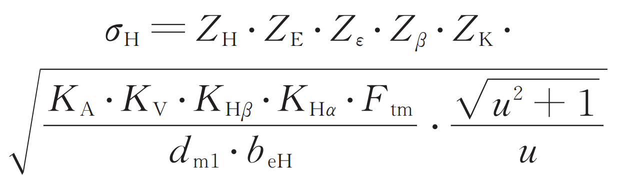
Where: σ H is the calculated contact stress; Z H is the node area coefficient; Ze is the elastic coefficient; Z ε The coincidence coefficient calculated for the contact strength; Is Z β Helix angle coefficient of contact strength calculation; K A is the service factor; K V is the dynamic load coefficient; K H β Tooth load distribution coefficient calculated for contact strength; K H α Tooth load distribution coefficient calculated for contact strength; FTM is the nominal tangential force on the indexing circle at the midpoint of the tooth width, FTM = 2000t1, 2 DM1, 2; DM1 is the end face of the middle point of the tooth width of the small wheel; Beh effective tooth width calculated by contact strength; U is the tooth ratio of spiral bevel gear; T1 and 2 are the acting torque on the pinion; DM1 and DM2 are the diameter of the indexing circle at the midpoint of the tooth width of the small wheel.
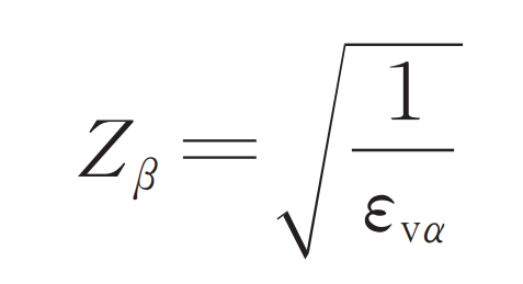
For several numerical calculation methods requiring special calculation, the calculation methods are as follows: ① Z β Coincidence coefficient of. According to the characteristics of spiral teeth studied in this paper, when the longitudinal coincidence degree of spiral bevel gear ε v β > 1, its value only coincides with the end face ε v α of The coincidence coefficient formula for the calculation of end face, longitudinal coincidence degree and contact strength is as follows:
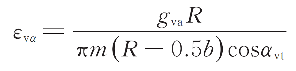
Where: GVA is the length of meshing line; α VT is the tooth profile angle of the end face; The radius of spiral bevel gear pitch is R; M is the end face modulus of the reference point.
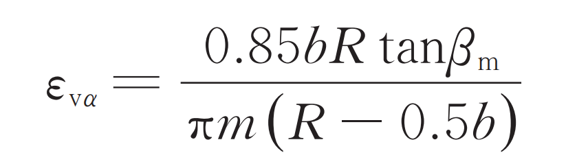
Where: β M is the helix angle.
② K v dynamic load coefficient:
Where: n is the critical speed ratio, i.e. the ratio of spiral bevel gear pinion speed n1 to critical speed ne1:
Where: Z1 is the number of teeth of spiral bevel gear; VTM is the mid point circumferential velocity.
When n ≤ 0.85, K value is:
Where: FPT is the dimensional limit deviation, which is usually taken according to the large wheel; y α Is running in quantity; C ‘is the stiffness of a single pair of teeth; Cv12 and CV3 are coefficients when n ≤ 0.85.
③ Allowable stress calculation. The calculation formula of allowable contact stress of orthogonal transmission spiral bevel gear is:
Where: σ HP is the contact fatigue strength of the test spiral bevel gear; σ Hlim is the contact fatigue limit of the test spiral bevel gear; Shmin is the minimum safety factor for contact strength calculation; ZL is the lubricant coefficient; Z V is the velocity coefficient; Zr is roughness coefficient; Z x is the dimension coefficient of contact strength calculation.