
| Parameters | Driving wheel | Driven wheel |
| Number of teeth | 29 | 48 |
| Modulus | 1.75 | 1.75 |
| Helix angle | 16 | 16 |
| Accuracy class | 7 | 7 |
The electric vehicle reducer gear of the collected load spectrum is helical gear, and the material is 20CrMnTi. Its main parameters and material properties are shown in Table 1 and table 2 below. According to experience, when the materials of helical gears are the same, the driving wheel is usually the first to suffer fatigue failure of helical gear pair, so the contact fatigue life of reducer gear is actually the contact fatigue life of driving wheel. To calculate the contact fatigue life of helical gears, it is necessary to obtain the contact stress time curve, which can be used for cycle counting. Previously, the output torque load of the drive motor has been obtained through the acquisition technology. To obtain the contact stress load spectrum of helical gears that can be used for fatigue calculation, some transformations need to be made, that is, the torque load of the drive motor collected is transformed into the contact stress of the upper tooth surface of the helical gears. This can be achieved by formula.
| Material Science | 20CrMnTi |
| Tensile strength | 1080Mpa |
| Yield strength | 835Mpa |
| Modulus of elasticity | 207GPa |
| Poisson’s ratio | 0.25 |

Where: K is the load coefficient, which includes the service coefficient Ka, the dynamic load coefficient kV, and the tooth direction load distribution coefficient K β, Load distribution coefficient K between teeth α, According to the reference, Ka = 125,KV =1.23,Kβ = 1.102,Kα= 1. 2. The calculation formula is as follows:

FT is the circumferential force;
B is the tooth width of driving gear;
D is the indexing circle diameter of the driving wheel, Z1 is the number of driving teeth;
εα Is the coincidence degree of helical gear section;
Ig is the tooth number ratio of helical gear pair;
ZH is the regional coefficient;
Ze is the elastic influence coefficient, and its value is related to the material, 20CrMnTi
The helical gear can be Ze = 189.8mpa1/2.
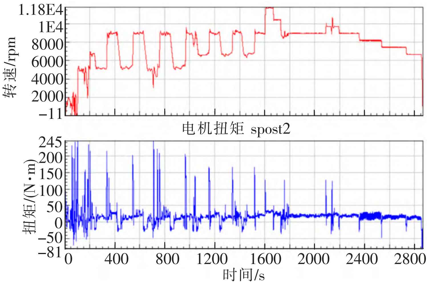
Figure 1 shows the measured motor output torque load spectrum. The torque shown in Figure 1 is substituted into the formula, and the helical gear contact stress load spectrum is calculated in ncode, as shown in Figure 2.
